| |
| Wind Turbine Bearings |
| There are many rotating parts in wind turbine, all of which use bearings. The most important of these are main shaft bearings, yaw bearing and pitch bearings. The structure of these bearings is different from ordinary bearings. This courseware will introduce its structure and characteristics. |
| Main shaft bearing |
Generally, there are two bearings on the front and back of the main shaft bearing. The force that the main shaft bearing bears mainly includes the weight of the rotor and the hub, and the force of the wind acting on the main shaft through the wind rotor. Therefore, the main shaft bearings are mainly subjected to radial forces and also to axial forces due to wind, due to the change of wind, the turbulence of the wind, the main shaft will bend and oscillate, and the main shaft can be rotated normally when the shaft is bent, that is, the bearing must have good self-aligning properties.
This courseware introduces the wind turbine main shaft front bearing. Its installation position is behind the rotor hub. The main force of the bearing is radial force and overturning moment. Spherical roller bearings have good self-aligning properties, allowing slight deflection and misalignment between the inner and outer rings when the bearings are in operation. Therefore, spherical roller bearings are widely used as main shaft bearings for wind turbine. Figure 1 is a structural view of a spherical roller bearing. |
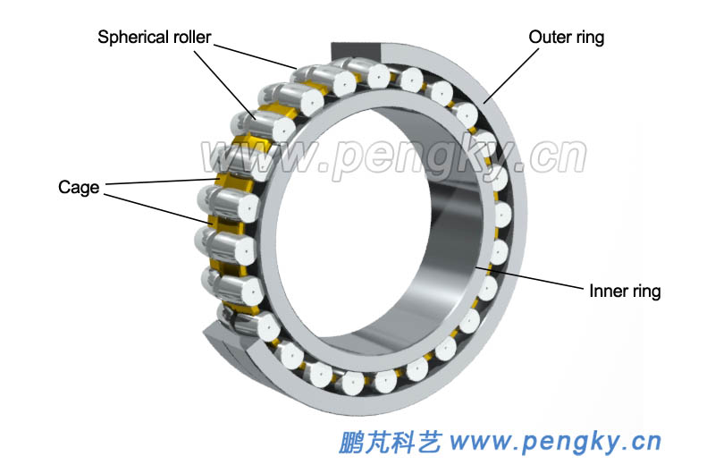 |
| Figure 1 - Spherical Roller Bearing |
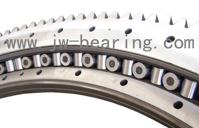
Like ordinary bearings, spherical roller bearings consist of an outer ring, an inner ring, a roller and a cage. The main feature is that the roller is different from the raceway.
The inner circumference of the outer ring of the spherical roller bearing is a spherical surface, and the center of the ball is at the center of the bearing. This spherical surface is the raceway. The bearing has two columns of rollers, sharing the spherical raceway of the outer ring, the roller is drum-shaped, and the drum surface is matched with the outer spherical raceway, called a spherical roller. Corresponding to the two columns of rollers, there are two raceways in the inner ring of the bearing, which are inclined at an angle to the bearing axis, as shown in the left figure of figure 2. The two columns of rollers can not only rotate around the bearing axis, but also rotate at the center of the bearing. The right figure of figure 2 is the state when the inner ring axis is inclined at 5 degrees to the outer ring axis, and the inner ring can still rotate freely around its own axis. Therefore, spherical roller bearings have self-aligning properties, also known as spherical roller bearings. Since the contact between the roller and the outer ring of the inner ring is that the wire is not a point, it can withstand the radial heavy load and the impact load. |
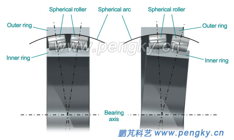 |
| Figure 2 - Spherical Roller Bearing |
| The spherical roller bearing is installed in the bearing pedestal, and the two sides are clamped by the bearing end-shield, and the bearing end-shield leaves a space where the inner ring and the roller are inclined (0.5 degree is sufficient), and figure 3 is a schematic diagram of the main shaft bearing structure of the wind turbine. |
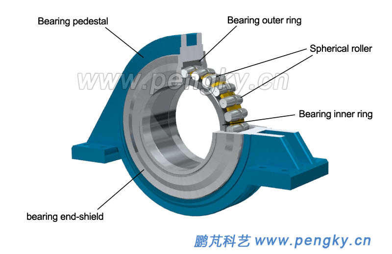 |
| Figure 3 - Wind turbine spindle bearing |
| Yaw bearing and slewing bearing |
The nacelle is mounted on the tower by the yaw bearing, and the blades are mounted on the hub via pitch bearings. These bearings are subjected to axial and radial forces and are subject to large overturning moments.
Figure 4 is a cross-sectional view of a yaw bearing. The bearing consists of an outer ring, an inner ring, a roller and a cage (the cage is not shown), and the roller uses a spherical roller. The difference from the ordinary bearing is that the raceway is different. |
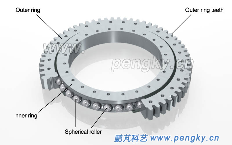 |
| Figure 4 - External tooth four-point contact ball bearing |
| The raceway of the inner and outer rings of the bearing adopts a peach-shaped cross section, as shown in figure 5 (to strengthen the difference, the ball is green), when there is no load or pure radial load, the steel ball and the inner and outer ring raceways are presented as four-point contact (red dot in the figure indicates the contact point position), so it is also called four-point contact ball bearing. When the bearing is subjected to radial force, the steel ball is subjected to force at four points, but when the axial load or the overturning moment acts, the steel ball and the inner and outer ring raceways become two-point contact. |
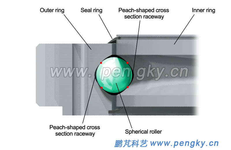 |
| Figure 5 - The raceway of a four-point contact ball bearing |
Four-point contact ball bearings are widely used in yaw bearings and pitch bearings of wind turbines when the axial load is large and the overturning moment is large. The bearing has a large diameter and a relatively small thickness relative to the diameter, which is also called a slewing bearing.
As the yaw bearing or pitch bearing of the wind turbine, the driving gear is usually made directly on the bearing ring. Figure 4 is the external gear four-point contact ball bearing, and the teeth are made outside the bearing outer ring; Figure 6 is the internal tooth four-point contact ball bearings, the teeth are made inside the inner ring of the bearing. |
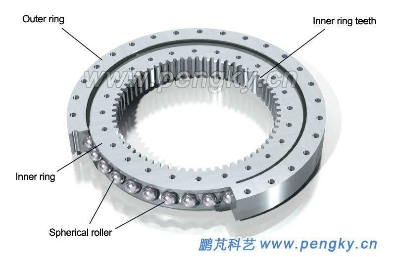 |
| Figure 6 - Internal tooth four-point contact ball bearing |
| The above slewing bearing has only one row of rollers, called single-row four-point contact ball bearing, some heavy-duty equipment should use double-row four-point contact ball slewing bearing. Figure 7 is a schematic diagram of the structure of a double-row four-point contact ball slewing bearing retransmitted from the network. |
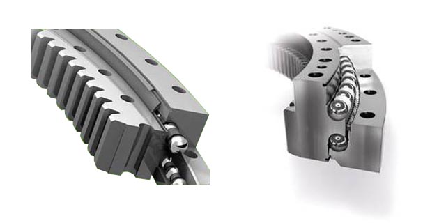 |
| Figure 7--Double-row four-point contact ball slewing bearing |
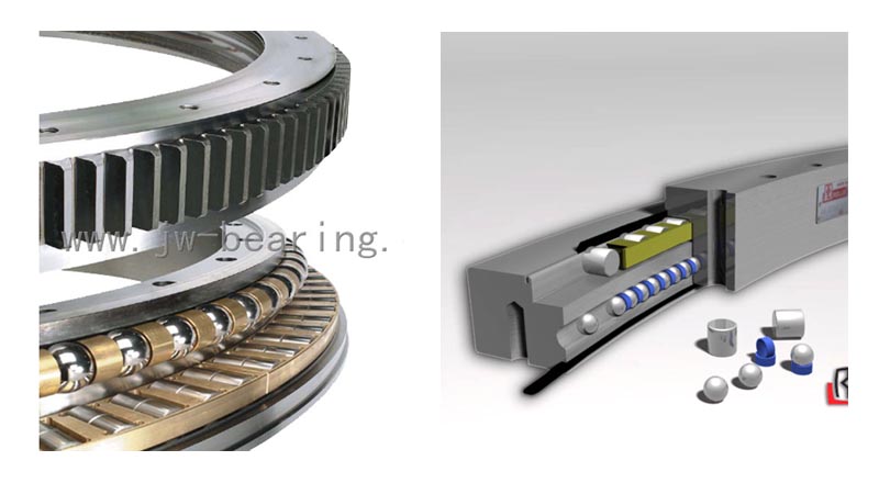
| The spherical roller is point contact, the bearing capacity is limited, the cylindrical roller is the line contact, and the bearing capacity is strong. In order to bear the multi-directional load at the same time, the cylindrical roller axis is arranged at 45 degrees with the bearing axis, and the adjacent rollers are arranged in a cross arrangement. (Perpendicular to each other), see figure 8 (the orange is the roller in the figure). Figure 9 is also a picture of the cross-cylindrical roller slewing bearing structure (pictures are from the network). With crossed cylindrical rollers, you can withstand larger loads. |
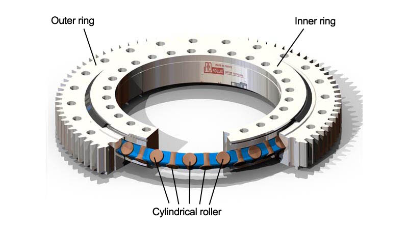 |
| Figure 8 - Cross cylindrical roller slewing bearing |
 |
| Figure 9--Cross cylindrical roller slewing bearing picture |
| For slewing bearings used in applications where the axial load is particularly heavy and the radial load is light, the rollers are combined with different rollers, the cylindrical rollers are used to bear the axial load, and the spherical rollers are used to bear the radial load, called the ball column combined slewing bearings, see figure 10 (pictures are from the network). The ball column combined slewing bearing mainly bears axial load and has poor ability to withstand overturning moment. |
 |
| Figure 10 - Ball column combined slewing bearing |
| In addition to the yaw bearing and pitch bearing of the wind turbine, the slewing bearing is also used for heavy equipment such as cranes, tower cranes, metallurgical mining machinery, and heavy industry. There are other structural forms of the slewing bearing, which will not be introduced here. |
| |
| Double row four-point contact ball bearing |
At present, the pitch bearing of large wind turbine is mostly double-row roller bearing with two rows of spherical rollers. Similar to the yaw bearing, the raceway adopts a four-point contact structure, so it is called a double row four points contact ball bearing.
The pitch bearing is installed between the blade and the hub. Similar to the yaw bearing, there are external gear bearing and internal gear bearing for electric driving pitch. There are also gearless bearing for hydraulic driving pitch or toothed belt drive pitch.
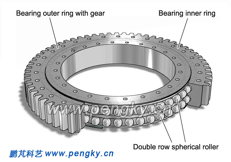
The double row four points contact ball bearing has a good bearing capacity for axial force, radial force and overturning moment. Figure 11 is showing the structure of an internal gear with double-row four-point contact ball bearing. The outer ring of the bearing is bolted to the hub, and the blade is bolted to the inner ring of the bearing. |
 |
| Figure11-- Double row four-point contact ball bearing (inner gear) |
Figure 12 shows the structure of an external gear double-row four-point contact ball bearing. The inner ring of the bearing is bolted to the hub, and the blade is bolted to the outer ring of the bearing. |
 |
| Figure 12-- Double row four points contact ball bearing (outer gear) |
|
| Double row tapered roller bearing |
Direct drive wind turbines do not configure a gearbox, and the main shaft is divided into two types: double-bearing structure and single-bearing structure. The single-bearing structure of wind turbine main shaft has only one bearing, because one bearing has a poor ability to withstand the overturning moment, the solution is to use a large-diameter bearing. At present, the diameter of the bearing used in the single-bearing structure has exceeded 3meters, and the double-row tapered roller bearing is adopted in wind turbine. Due to the included angle between the roller axis and the bearing axis, the bearing can carry axial load, the larger the included angle is, the stronger the axial load capacity is. The rollers are conical, and all the projection lines of the roller cone surface intersect at the same point on the bearing axis. So this kind of bearing has good bearing capacity of axial load, radial load and overturning moment.
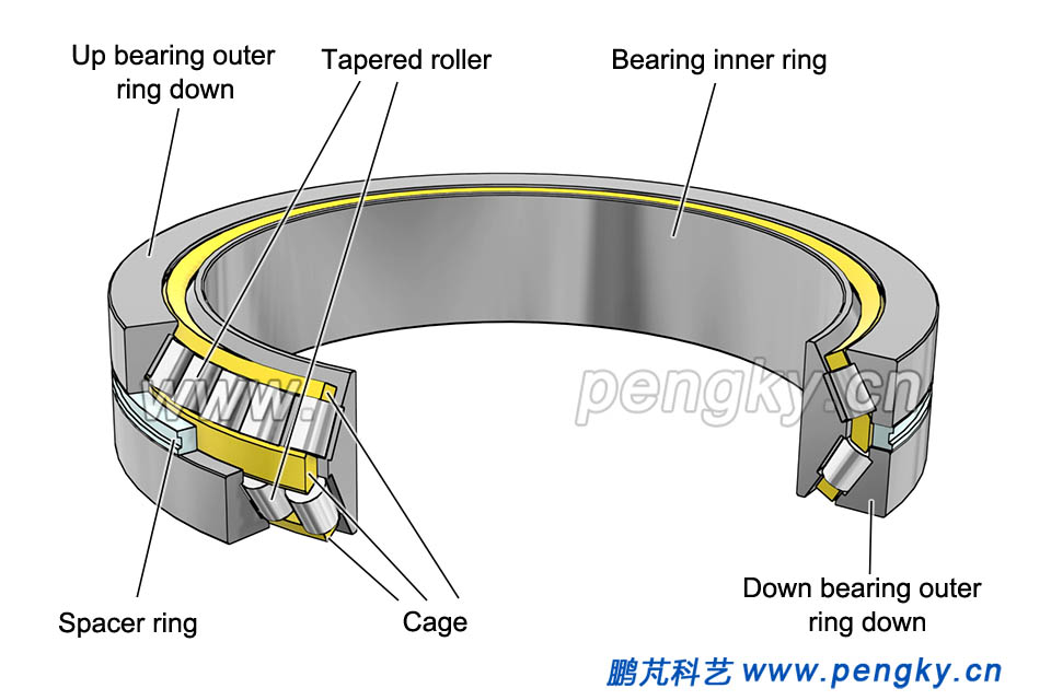
Figure 13 is a double-row tapered roller bearing with a double outer ring. For installation, the outer ring of the bearing is composed of two joints and assembled in combination and there is a spacer ring between the two outer rings, the thickness of the spacer ring is changed to adjust the clearance of the bearing. Bearing clearance is the gap between the bearing rollers and the inner and outer rings of the bearing. |
 |
| Figure 13-- Double row tapered roller bearing with double outer ring |
Figure 14 is a double-row tapered roller bearing with double inner rings. The inner ring of the bearing is composed of two combined and assembled. There is a spacer ring between the two inner rings. The thickness of the spacer ring can be changed to adjust the bearing's travel. Gap.
The outer ring and inner ring of the bearing have mounting bolt holes for easy axial installation. |
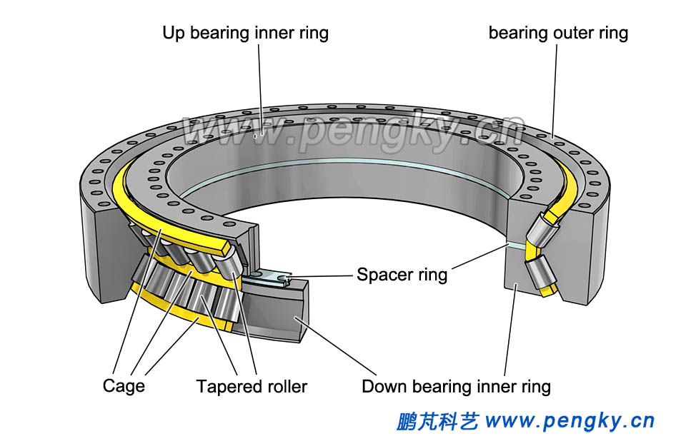 |
| Figure 14-- Double row tapered roller bearing with double inner ring |
| |

