| |
| Doubly-Fed Wind Turbine Working Principle |
The variable speed operation of the wind turbine can make the wind turbine absorb the wind energy to the maximum extent and improve the operating efficiency of the wind turbine. The large-capacity variable-speed constant-frequency wind turbine system is the mainstream direction of the wind power technology, but the variable-speed constant-frequency wind turbine using the doubly-fed asynchronous generator is still the mainstream model. The basic structure is described in the generator construction column "Doubly-fed wind generator construction" section using a model of a doubly-fed wind generator. Figure 1 is a picture of the doubly-fed wind generator model. |
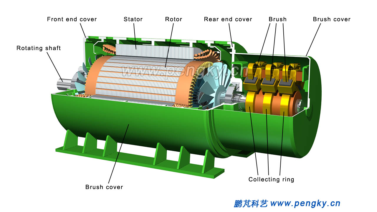 |
| Figure 1 - Cutaway view of the doubly-fed asynchronous generator |
This section only briefly introduces how the doubly-fed wind turbine achieves the principle of variable speed constant frequency.
The wind speed is unstable. The wind rotor speed of the wind turbine is in constant fluctuation. The rotor speed of the generator that has been increased by the speed increase gearbox is constantly changing. The frequency of alternating current generator generated by the ordinary alternator is also constantly changing.
The alternator wants to output a stable voltage, it is necessary to keep the rotor speed stable, that is, to ensure the stability of the rotating magnetic field in the generator. The magnetic field generated by the AC synchronous generator rotor is constant with respect to the rotor, the generator speed changes, and the frequency of the output voltage changes. This problem can be solved if the magnetic field generated by the rotor can be rotated relative to the rotor, that is to say the rotor speed change does not affect the rotation speed of the rotating magnetic field.
For example, for a single-pole generator with an output voltage of 50 Hz, the internal rotating magnetic field has a rotation speed of 50 rev / sec, and for a conventional 2-pole generator, the rotor is also 50 rev / sec, and the rotating magnetic field is synchronized with the rotor.
When the rotor speed becomes 30 rev / sec, the rotor generates a rotating magnetic field of 20 rev / sec. After the rotating magnetic field is superimposed with the rotor speed of 30 rev / sec, the rotating magnetic field of 50 rev / sec is opposite to the stator, and 50 Hz AC power can be emitted.
The same principle, when the rotor speed becomes 60 rev / sec, the rotor produces a reverse rotation magnetic field of 10 rev / sec, the superposition of the two speeds can produce a rotating magnetic field of 50 rev / sec, can emit 50 Hz AC.
The rotor of the doubly-fed asynchronous generator is wound with a three-phase winding, and the three-phase alternating current is input to the rotor winding to make the rotor generate a rotating magnetic field relative to the rotor, and the above functions can be completed.
Figure 2 is an animated screenshot of the rotor and stator and rotating magnetic field of a doubly-fed asynchronous generator. It is a schematic diagram of a 2-pole generator.
The left picture shows the magnetic field generated by the rotor and the rotor. The magnetic field is represented by two purple magnetic lines of force. The animation shows the rotation of the magnetic field relative to the rotor (the rotor itself does not rotate); the diagram on the right shows the rotor in the stator, demonstrating how the rotor with a rotating magnetic field ensures that the rotate speed of the magnetic field relative to the stator is constant. |
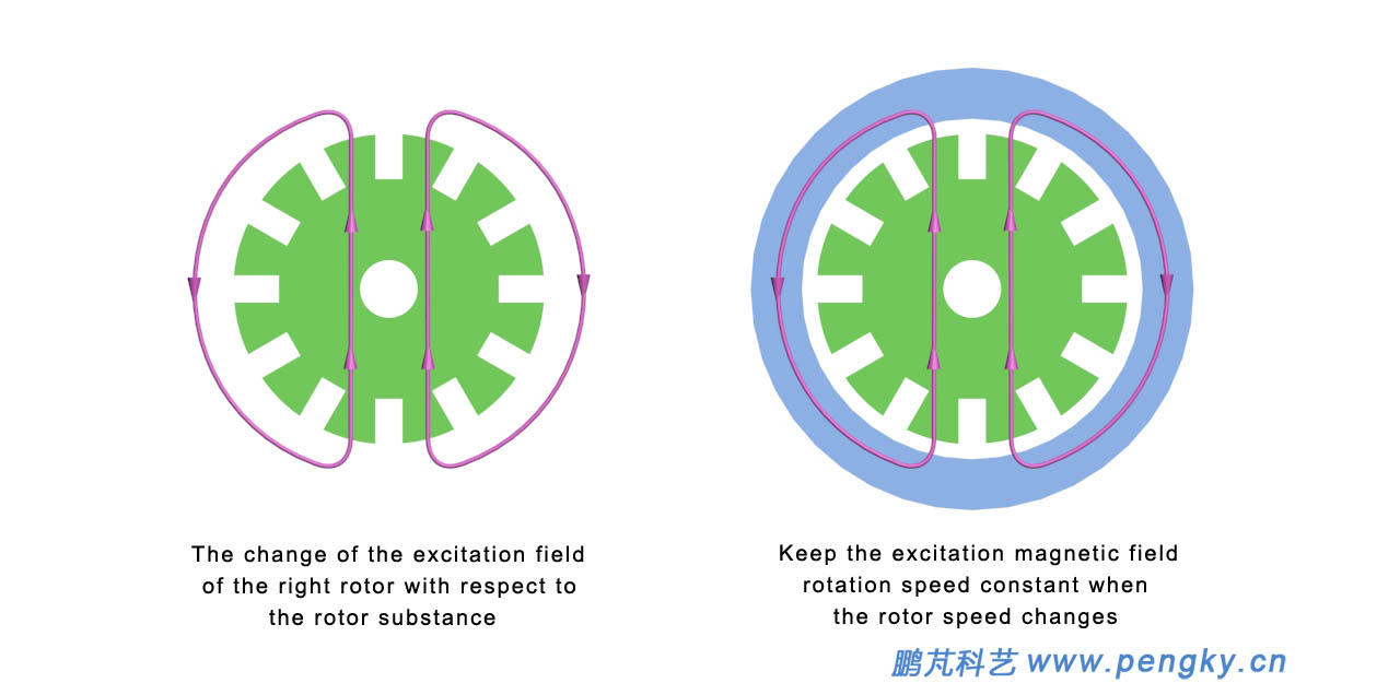 |
| Figure 2 - Rotating magnetic field of doubly-fed asynchronous generator |
Notes of the demo animation:
In order to emit 50 Hz of alternating current, the rotation speed of the internal rotating magnetic field of the generator must be 50 rev / sec.
When the rotor is 50 rev / sec, the rotating magnetic field is stationary with respect to the rotor, the left animation is stationary, and the right animated rotor rotates synchronously with the magnetic lines of force. This operating state is synchronous speed operation.
When the rotor speed is reduced to 30 rev / sec, the rotor produces a rotating magnetic field of 20 rev / sec, the magnetic field in the right animation is rotated at 20 rev / sec, the rotor speed in the left animation is 30 rev / sec, the combined magnetic field speed is 50 rev / sec, this operating state is sub-synchronous speed operation.
When the rotor speed rises to 70 rev / sec, the rotor produces a reverse rotation magnetic field of 20 rev / sec, the magnetic field in the right animation rotates 20 rev / sec in the opposite direction, and the rotor speed is 70 rev / sec in the left animation. The combined magnetic field speed is 50 rev / sec, and this operating state is super synchronous speed operation.
Please watch this demo animation below. In order to clearly see the changes in the animation, the speed in this animation is about 1/375 of the actual speed. |
| Doubly-fed asynchronous generator rotating magnetic field demonstration animation |
 |
The doubly-fed wind turbine is mainly composed of a wind rotor, a speed increasing gearbox, a doubly-fed asynchronous generator, an AC-DC-AC converter, a transformer, a power switch, etc., and the connection is shown in figure 3. The wind rotor drives the generator after the speed increase, and the generator stator winding wire end is the generator power output end, and is connected to the AC power grid through the switch box; the generator rotor winding is connected to the AC-DC-AC converter through the collecting ring. The other end of the converter is connected to the transformer, and the other end of the transformer is connected to the AC grid through the switch box. The main functions of the AC-DC converter are described later in this section.
The system thus constructed can operate normally when the generator speed is lower than 40% of the synchronous speed and 15% higher than the synchronous speed. |
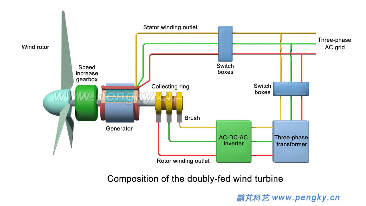 |
| Figure 3 - Composition of the doubly-fed wind turbine |
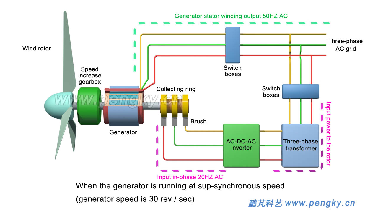
| When the generator rotor is in sub-synchronous operation, if the speed is 30 rev / sec, lower than the synchronous speed of 20 rev / sec, the grid inputs 20 Hz AC power through the AC-DC-AC converter to the generator rotor winding, resulting in relative rotor 20 rev / sec rotating magnetic field, together with the rotor to produce a synthetic magnetic field of 50 rev / sec, so that the stator windings emit 50 Hz AC, the electric power flow to see figure 4. |
| Figure 4 - Sub-synchronous operation rotor power flow of doubly-fed wind turbine |
| When the generator rotor is in synchronous operation, the rotation speed is 50 rev / sec, and the grid inputs DC power to the generator rotor winding through the AC-DC-AC converter, generating a fixed magnetic field relative to the rotor, so that the stator winding emits 50 Hz AC power. The electric power flow is shown in figure 5. |
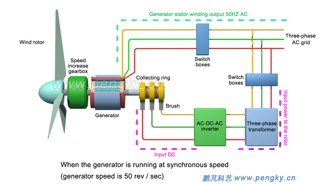 |
| Figure 5 – Rotor power flow of synchronous operation of doubly-fed wind turbine |
| When the generator rotor is in super-synchronous operation, if the speed is 60 rev / sec, higher than the synchronous speed of 10 rev / sec, the generator rotor winding induces a reverse-phase 10 Hz AC, AC-DC-AC converter The 10 Hz reverse phase alternating current is converted to 50 Hz alternating current and sent to the grid through a transformer. Since the 10 Hz alternating current induced by the rotor winding is reversed from the alternating current generated by the stator winding, the rotor generates a reverse rotating magnetic field of 10 rev / sec with respect to the rotor, which together with the rotor produces a combined magnetic field of 50 rpm. The stator windings emit 50 Hz of AC power, and the power flow is shown in figure 6. |
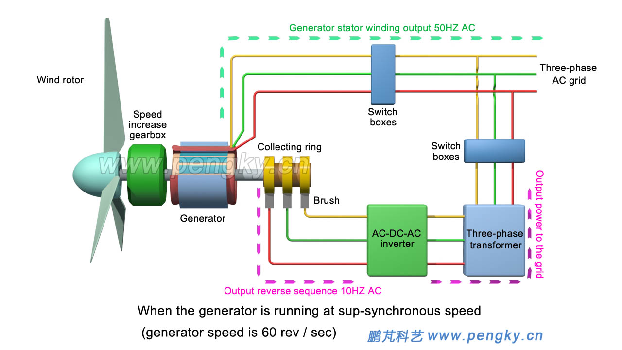 |
| Figure 6 - Super-synchronous operation rotor power flow of doubly-fed wind turbine |
| Let's look at the running animation of the doubly-fed wind turbine generated by the above picture. In order to clearly demonstrate the change of the motor speed in the animation, the animation exaggerates the speed change. If the animation is reversed, please download it to your local computer for playback. |
| Doubly-fed wind turbine running variable speed animation |
|
AC-DC-AC converter is a kind of inverter equipment. It adopts two PWM inverter circuits back to back. It is called bidirectional PWM inverter circuit or bidirectional converter. The inverter circuit connected to the collecting ring of the generator is called generator side converter, the inverter circuit connected to the grid side is called a grid side converter. Input alternating current on one side of the bidirectional converter can convert alternating currents of different frequencies, different voltages and different phases on the other side; the reverse direction is also the same.
High-power AC-DC-AC converters are very expensive. The AC-DC-AC converters in the doubly-fed wind turbines only provide excitation power to the rotor windings, and the power is 25% of the generator is sufficient. Relatively full power converters are much cheaper, which is one of the main advantages of doubly-fed wind turbines.
Figure 7 is a schematic diagram of the main circuit of the doubly-fed wind turbine generator. Please refer to the data for the working principle. |
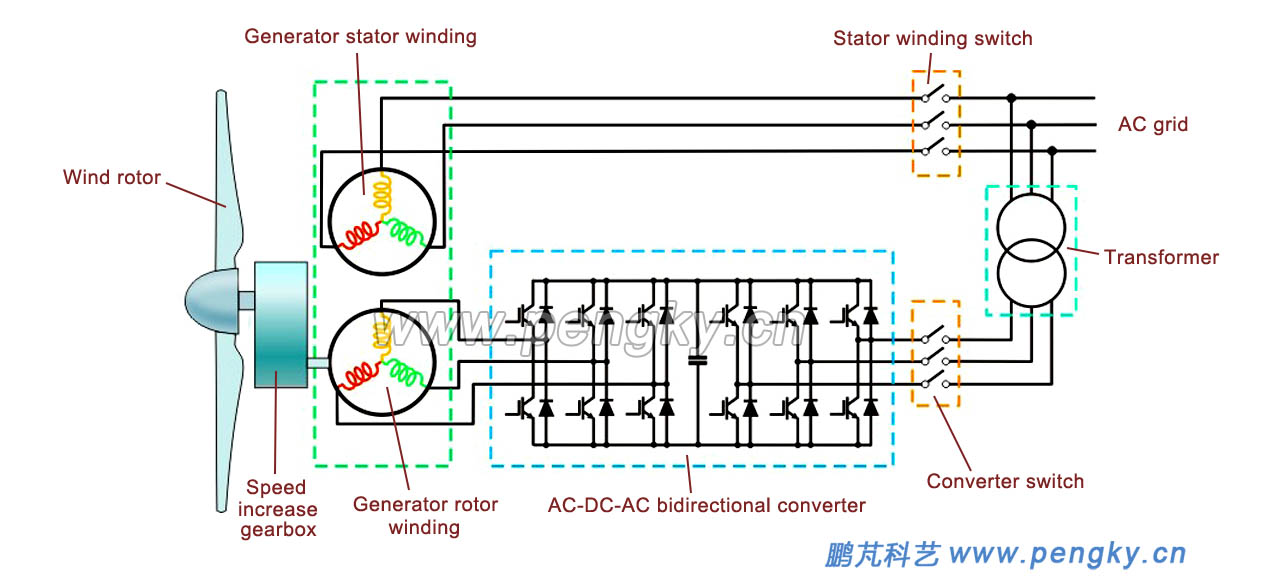 |
| Figure 7 - Schematic diagram of the main circuit of the doubly-fed wind turbine |
| |
|