
| Independent Pitch System |
The principle of pitch adjustment speed is introduced in the wind turbine speed control courseware, and a simple centrifugal force pitch adjustment device is also introduced. Modern large and medium-sized wind turbine have high requirements on the pitch performance of the blades to ensure that the wind turbine can operate at the highest efficiency and safety, mainly including independent pitch system and uniform pitch mechanism. This courseware introduces the independent pitch system. The pitch system should ensure that the rotor blades have a good pitch angle function in the starting state, normal operating state, and shutdown feathering state, that is: Operating state: In normal operation, when the power is below the rated power, the pitch angle is around 0 degree; when the power exceeds the rated power, increase the angle of attack convergence according to the computer command, and continuously adjust the pitch angle to make the generator output power is maintained near the rated power and the pitch angle varies between 0 and 30 degrees. Shutdown feathering state: When the turbine is normally stopped and fast stopped, the blade is feathered to near 90 degrees, and the rotor speed is reduced to 0 by the aerodynamic drag of the blade. In the event of a power outage or failure, the computer can automatically enter the fully feathered state without a computer command, so that the wind turbine can be emergency shutdown to ensure the safety of the wind turbine. The pitch angle of the three sets of blades of the pitch system introduced in this courseware is controlled by the respective drive unit, and the blades of one wind turbine can make different pitch angle changes according to different controls. This pitch system is called an independent pitch system and has good control performance. There are mainly hydraulic drive and electric drive. |
| 1. Hydraulic pitch system |
| First introduce the hydraulic pitch system. There are three pitch bearing flanges on the three-forked hub of the wind rotor, which will be fixedly mounted with the outer ring of the pitch bearing. The three-forked hub in figure 1 is cut open, two pitch bearings have been fixed on the two flanges, and the blade root plate is fixed in the inner ring of one pitch bearing. The blade root is fixedly connected with the blade root plate, and the blade can be freely rotated through the pitch bearing. There is a hydraulic cylinder in the figure. The hydraulic cylinder has an extensible piston rod (hydraulic rod). The output of the piston rod is connected with the pitching handle on the blade root plate through the hydraulic rod bearing. The expansion and contraction of the piston rod pushes the blade root plate to rotate. Since the pitching handle is a circular motion, the hydraulic cylinder will also oscillate, so the hydraulic cylinder is mounted on the hub through a swinging shaft. |
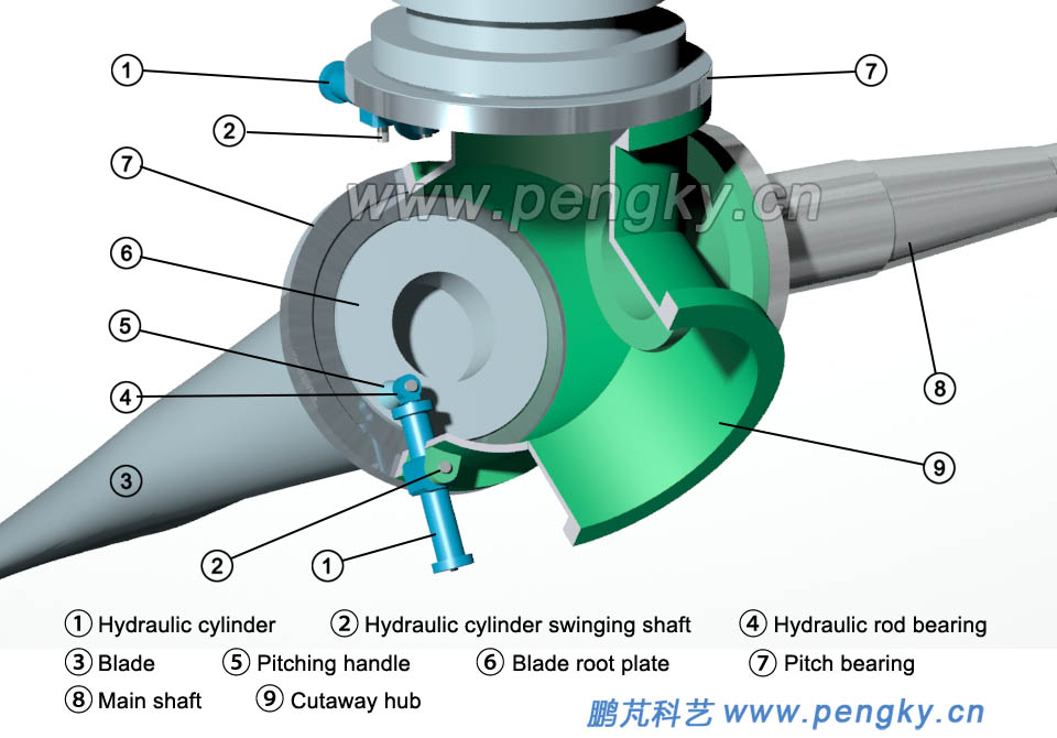 |
| Figure 1 - Hydraulic cylinder of hydraulic pitch system |
| Figure 2 is a state in which the piston rod portion of the hydraulic cylinder is pushed out, and the blade is rotated by a certain angle. |
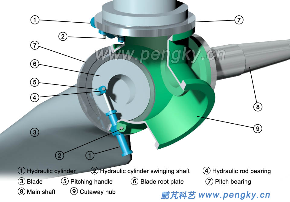 |
| Figure 2 - Hydraulic pitch device adjusts pitch |
| Figure 3 is a state in which the piston rod of the hydraulic cylinder is fully pushed out, and the blade is rotated to the Pitch angle is 0. |
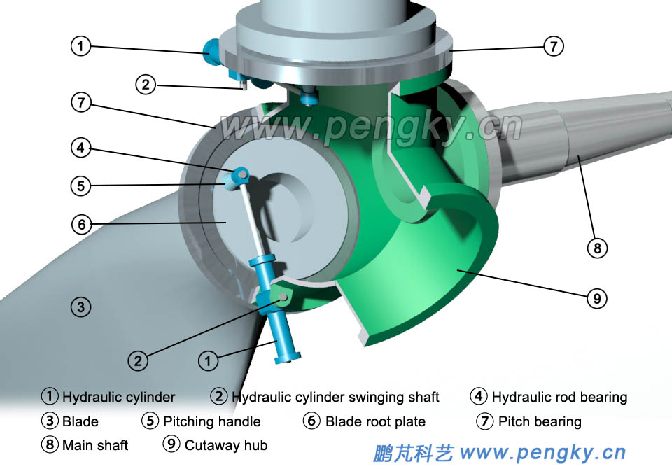 |
| Figure 3 - Pitch angle is 0 of hydraulic pitch device |
| Figure 4 is a schematic view of a hydraulic pitch system with three sets of blades installed. |
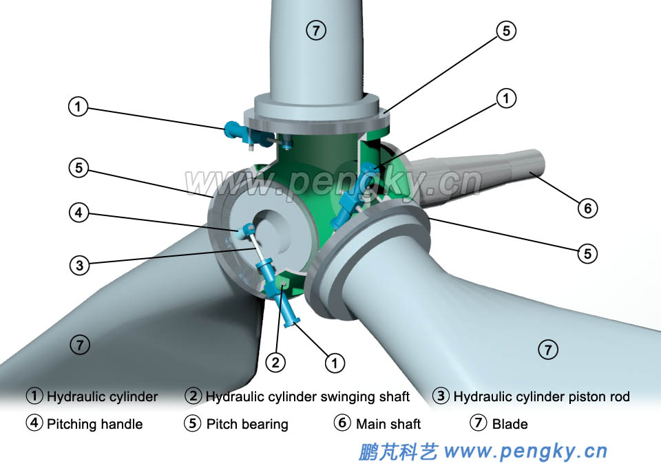 |
| Figure 4--Hydraulic pitch system |
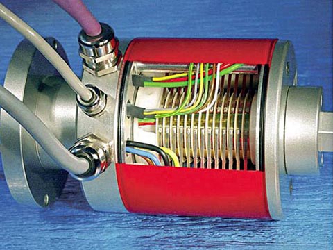
In order to accurately control the rotation angle of the blade, a linear displacement sensor is provided in each hydraulic cylinder, and the rotation angle of the blade can be known according to the measurement of the moving distance of the piston rod. The hydraulic tubes and signal cables pass through the through hole of the main shaft and gearbox and are transmitted to the nacelle controller through the slip ring transmission. The figure 5 left is a multi-path hydraulic transmission slip ring (rotary joint), and the figure 5 right is an integrated slip ring for hydraulic transmission and electrical transmission, which can simultaneously transmit liquid and electrical signals. The picture is from the web. The slip ring transmission device is mounted at the rear of the gearbox, and the rotating part is connected to the through pipe from the main shaft end. |
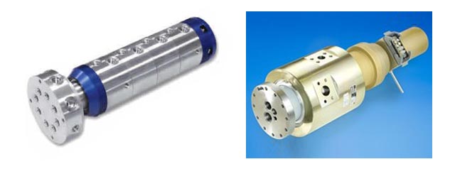 |
| Figure 5 - Rotating joint and slip ring |
| The hydraulic pitch device performs the pitch operation well according to the computer command when the wind speed exceeds the rated wind speed and is lower than the cut-out wind speed to ensure that the wind turbine runs near the rated speed; When the wind speed exceeds the cut-out wind speed, it can enter the full feathering state, and it can automatically enter the full feathering state in the event of power failure or other faults. |
| 2. External gear electric pitch system |
| Figure 6 shows the hub of the external gear electric pitch system. Three pitch bearings are mounted on the wind turbine hub. The outer ring of the bearing is fixed to the hub. The outer ring of the bearing is integrated with the pitch gear. The teeth of the gear are on the outer circumference. The inner ring of the bearing can be rotated in the outer ring. |
 |
| Figure 6--External gear electric pitch system hub |
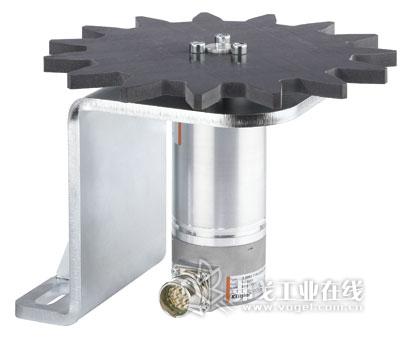
| The pitch drive motor can be a DC or AC actuating motor, which is driven by a large proportion of the gearbox and then drives the pinion. Figure 7 is a picture of the pitch motor downloaded from the Internet. |
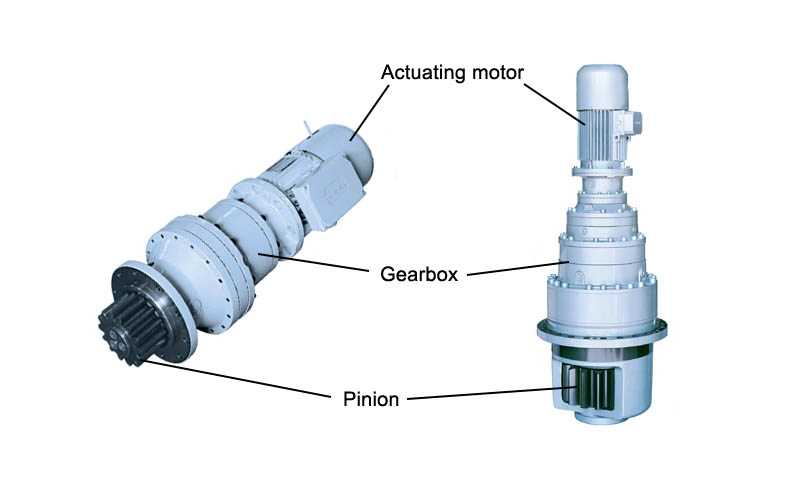 |
| Figure 7--Pitch motors drive motor |
| Each of the three blades has a pitch drive motor and a pinion on the shaft, and the pinion and the pitch gear mesh. The relative position is shown in figure 8. |
 |
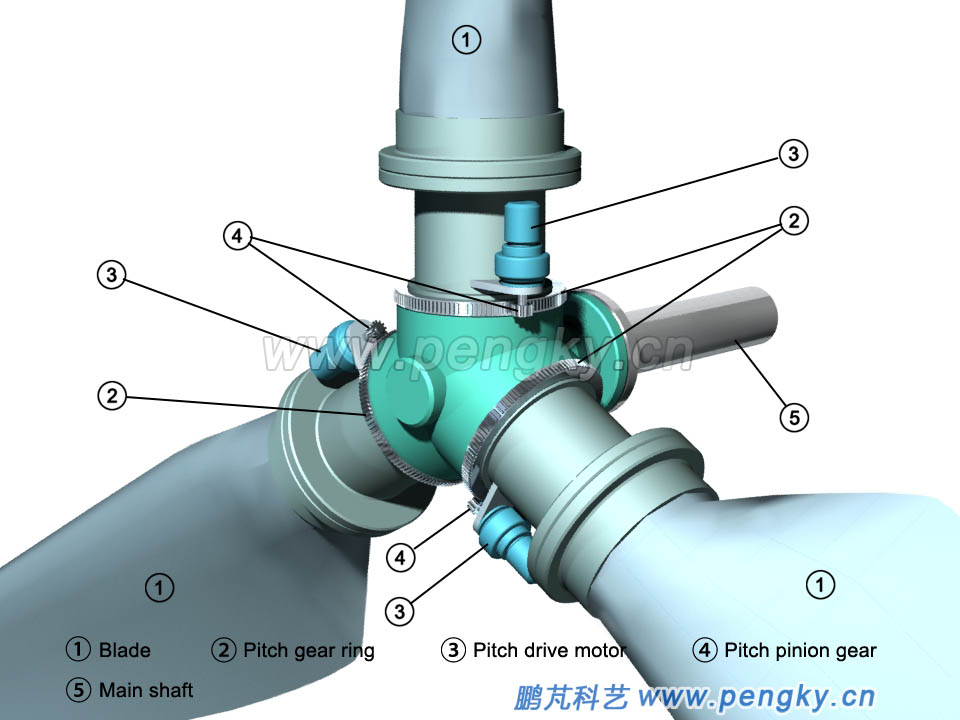
| Figure 8 - External gear bearing pitch motor |
| The pitch drive motor is mounted at the blade root, and the pinion gear on the motor shaft meshes with the pitch gear. When the motor rotates, the blade rotates to change the pitch angle. The pitch drive motors of the three blades are relatively independent from the related components and can be operated separately. This is the independent electric pitch system. The pitch angle of the three blades is controlled by computer control. |
 |
| Figure 9--Electric pitch device operation |
The drive power and control device of the pitch motor is mounted in the hub, and the power and control signal wires are connected to the control cabinet of the nacelle through the through hole of the main shaft and the through hole of the gear box through the slip ring device. The following is a 3D animation of the external gear pitch system. The front part of the animation demonstrates the pitch motion of the wind turbine blade. The rear stage of the animation demonstrates that the pitch motor drives the blade to perform the pitching action. In order to see the blade rotation, the blade adopts a semi-transparent display with a wire frame. |
| Animation 1 - external gear electric pitch system |
 |
| 3. Internal gear electric pitch system |
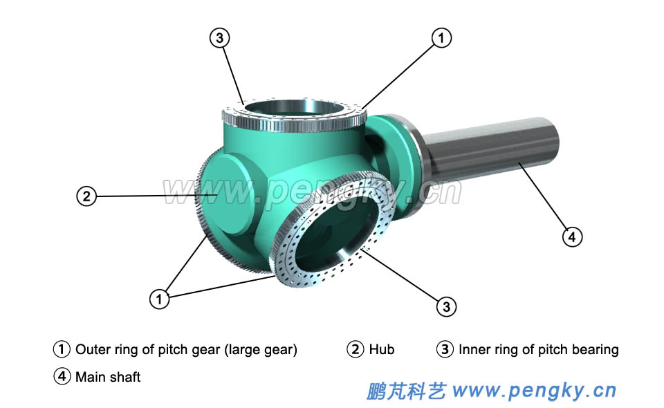
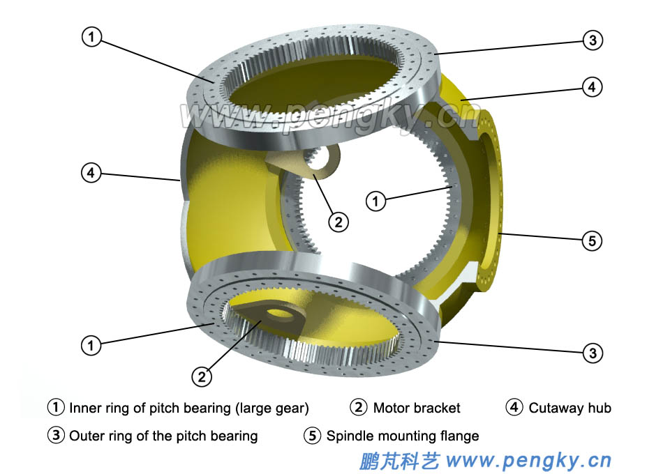
| Figure 10 is a hub view of an electric pitch system using an internal gear. Three pitch bearings are mounted on the circumference of the hub. The outer ring of the bearing is fixed to the hub, and the inner circumference of the bearing inner ring is integrated with a pitch gear (large gear). The blade will be mounted on the inner ring of the bearing. |
 |
| Figure 10 - Pitch internal gear bearing and hub |
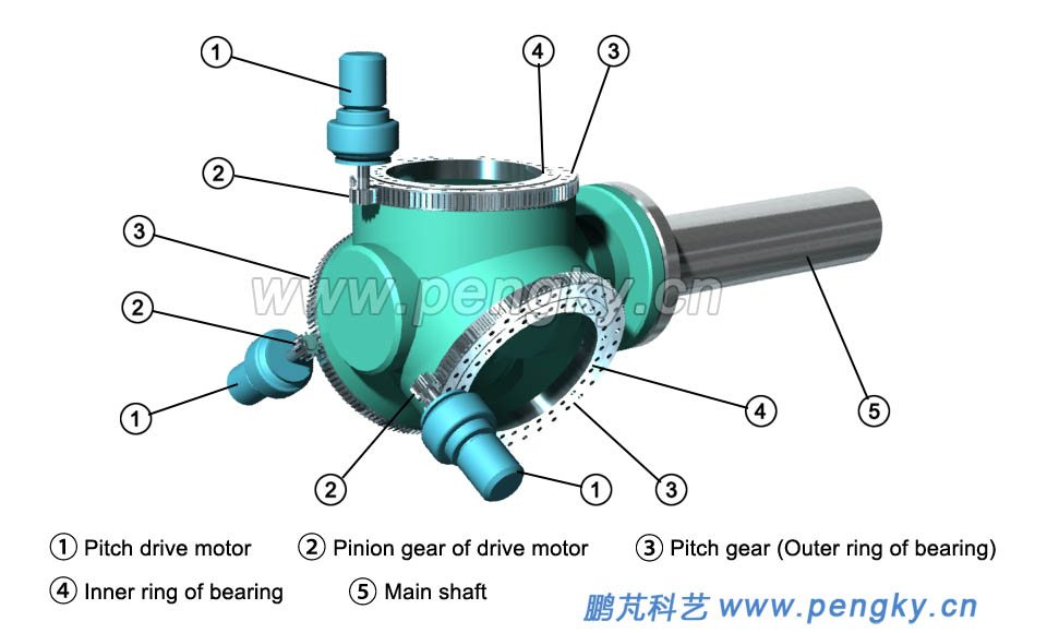
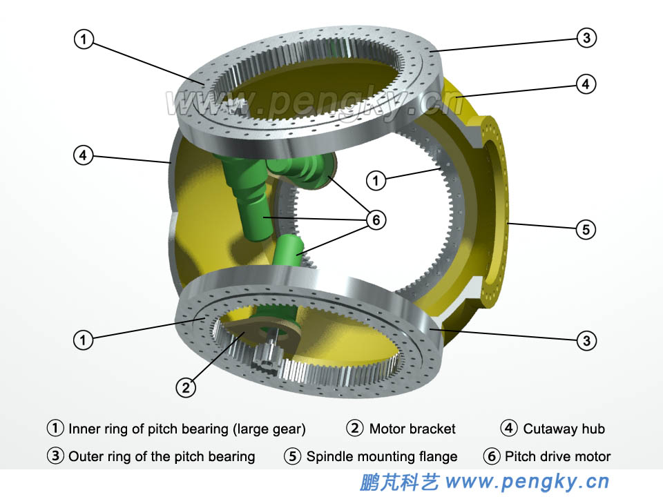
| Three pitch drive motors are mounted in the hub, and the pinion gears on the motor shaft mesh with the pitch gears. The pitch angle can be changed by pushing the pitch gear to rotate as the motor rotates, as shown in figure 11. |
 |
| Figure 11 - Pitch internal gear bearing and drive motor |
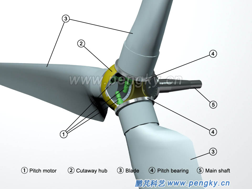
| Install the three blades on the inner ring of the three bearings through the root bolts, see figure 12, which is a screenshot of the internal pitch bearing electric pitch animation. |
 |
| Figure 12 - Internal gear bearing electric pitch system |
Since each of the three blades has a set of pitch motor and related components, which can operate independently, it is called an independent electric pitch system. Although the three pitch devices are independent, their pitch angles are controlled synchronously by the cabin computer control. The following is a 3D animation of the internal gear pitch system. The front section of the animation demonstrates that the hub bearing large gear rotates under the driving of the pitch motor. In the latter part of the animation, the pitch motor drives the blades to perform the pitching action. In order to see the blade rotation, the blade adopts a semi-transparent display with a wire frame. |
| Animation 2--Internal Gear Electric Pitch System Animation |
|
| 4. Auxiliary device |
| The driving power source and control device of the pitch motor are installed in the hub. Since the hub is rotating continuously, the power cable, signal cable and control cable of the pitch system cannot be directly connected to the nacelle. These cables are connected to the control cabinet of the nacelle through the main shaft through hole and the gear box through hole and through the slip ring device. Figure 13 is a cutaway view of the slip ring device (picture from the network). |
 |
| Figure 13 - Slip ring |
| An accumulator is installed in the hub, and each pitch device also includes a motor driving power source, a blade angle transducer, and a limit switch. The motor driving power source outputs current according to a computer command to operate the motor. The blade angle transducer meshes with the pitch bearing gear through a pinion gear, and the blade angle is measured by an encoder and a counter on the transducer. Figure14 is a blade corner transducer. |
 |
| Figure 14 - Blade angle transducer |
The pitch motor can be a DC motor or a three-phase AC motor or a brushless permanent magnet motor. The motor must have a magnetic brake device to ensure that the motor is in a braking state when the motor is stopped, ensuring that the pitch angle is constant. When the grid is powered down, the motor driving power source power the motor by using accumulator power and automatically enters the feathered shutdown state. More independent pitch systems are used in large and medium-sized wind turbines now. There are also many medium-sized wind turbines that use a uniform pitching method. Commonly used are the drive rod unified pitch drive mechanism and the gear unified pitch drive mechanism. Please refer to the relevant courseware. |
| Back to Previous Page |
