
| Wind Turbine Yaw Device | ||
In the section "Composition and Form of Horizontal Axis Wind Turbine", introduced to facing the wind mode of the horizontal axis wind turbine. Here again introduce the tail vane facing the wind and the side wind rotor facing the wind, and then focus on the yaw system. |
||
| Tail vane facing the wind | ||
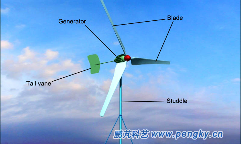
| In small wind turbines, the tail vane facing the wind is generally used for wind. Figure 1 is a small wind turbine that uses a tail vane facing the wind. | ||
 |
||
| Figure 1 - Tail vane facing the wind of small wind turbine | ||
| Below is a 3D animation of a small wind turbine running with the tail vane facing the wind | ||
 |
||
| Animation 1--Tail vane facing the wind of small wind turbine 3D animation | ||
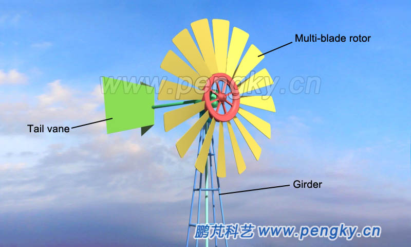
| Many agricultural multi-blade rotor wind turbines also use the tail vane facing the wind. Some tail vane are two-leaf styles, which have greater resistance to the facing the wind to against the resistance of the multi-leaf rotor and ensure a stable wind. See figure 2. | ||
 |
||
| Figure 2 - Multi-leaf rotor wind turbines also use tail vane facing the wind | ||
| Side wind rotor facing the wind | ||
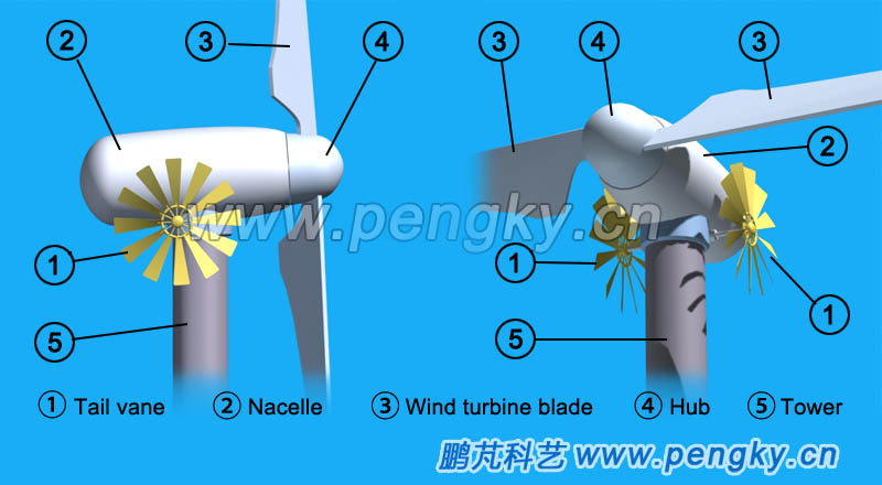
| The structure of side wind rotor facing the wind has two side wind rotors (steering rotors) on both sides of the rear part of the nacelle. The two side wind rotors are generally on the same revolving shaft, and the horizontal direction of the revolving shaft is perpendicular to the wind turbine main shaft. When the wind turbine is accurately facing the wind, the planes of the two side wind rotors are parallel to the wind direction., and the side wind rotor does not rotate; when the wind turbine is not facing the wind, the side wind rotor rotate at an angle with the wind, and pushes the nacelle rotating through the gear or the worm gear until the wind turbine wind rotor facing the wind, The figure 3 left is the side wind rotor facing the wind, wind turbine side view, and the right side is the side wind rotor facing the wind, wind turbine perspective view. | ||
 |
||
| Figure 3 - Schematic diagram of the side wind rotor facing the wind | ||
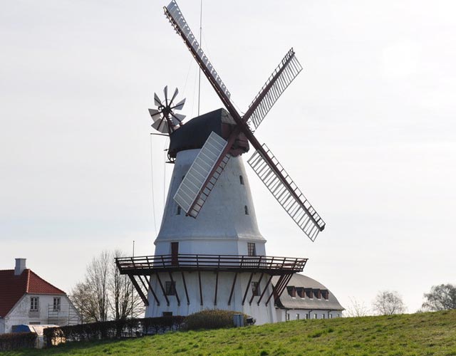
The side wind rotor facing the wind has a complicated structure, and the advantage is that it can face the wind when there is no electricity. Side wind rotor facing the wind are also used in windmills in the Netherlands. Figure 4 is a picture of a Dutch windmill using side wind rotor facing the wind (picture from the network). |
||
 |
||
| Figure 4 - Dutch windmill with side wind rotor facing the wind | ||
| Wind measurement system | ||
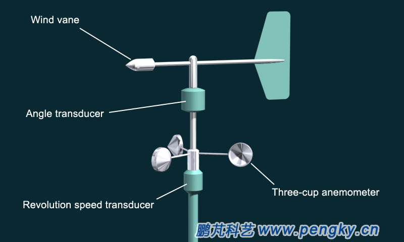
Wind turbine want to capture wind energy to the greatest extent, it must accurately face the wind. Wind turbine must know the wind direction accurately. Therefore, measuring wind direction is the first thing. When to reach the cut-in speed to start the wind turbine, when to enter the rated speed, when to reach the cut-out speed to stop the wind turbine, the maximum power and the pitch angle adjustment need to know the wind speed, so measuring the wind speed is also essential. Generally, the wind turbine cut-in speed is about 3m/s to 4m/s; the rated speed is determined according to the specific conditions of the wind power plant, most of which are from 12m/s to 14m/s; the cut-out wind speed is mostly 25m/s. In the section "Wind Measurements", the wind vane, three-cup anemometer, pitch wind speed and direction anemometer, ultrasonic wind speed and direction have been introduced. Due to its low cost and easy maintenance, the mechanical wind speed and direction anemometer is still widely used in wind turbine. Figure 5 is a wind speed and direction anemometer (wind direction wind speed transducer). |
||
 |
||
| Figure 5 - Wind direction and speed transducer of wind turbine | ||
| The anemometer is installed on the top of the rear of the nacelle, and the left and right sets are mutually standby and mutually verified. | ||
| Yaw System | ||
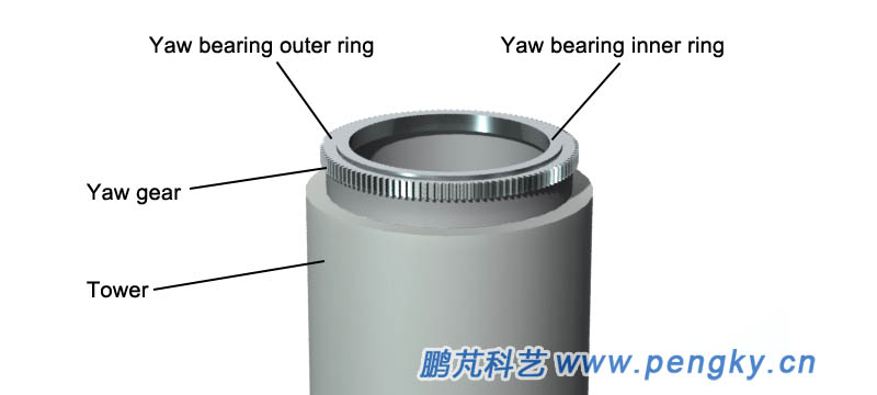
For the larger wind turbine, facing the wind is more complicated. The wind rotor is installed at the front-end of the nacelle, and the nacelle is installed on the tower. The nacelle can rotate with the tower axis as the axis, so that the wind rotor faces the incoming wind. A set of equipment is installed between the nacelle and the tower to achieve wind turbine facing the wind. This set of equipment is called yaw system. It includes yaw bearing, yaw gears, drive motors, control system devices and wind measurement devices. The structure of a common yaw system is described below. A yaw bearing is mounted on the tower flange at the top of the tower. The outer ring of the yaw bearing is fixed at the top of the tower, and the inner ring of the yaw bearing is used to mount the nacelle chassis. The yaw bearing has a strong axial bearing capacity, can withstand radial impact force and overturning moment, and integrates a yaw gear on the outer periphery of the yaw bearing outer ring, as shown in figure 6. |
||
 |
||
| Figure 6 - Tower and yaw bearing | ||
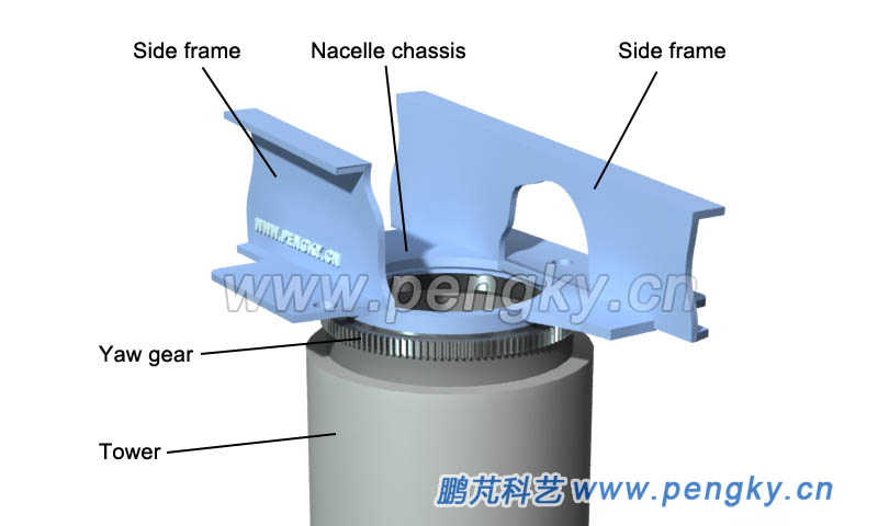
| The nacelle chassis is mounted on the inner ring of the yaw bearing. The nacelle chassis is the base of the wind turbine main shaft, gear box, generator, etc., also called the frame, see figure 7 (only the middle part of the frame is shown). The nacelle chassis can be rotated by the yaw bearing with the tower axis as the axis. | ||
 |
||
| Figure 7 - Nacelle chassis and tower | ||
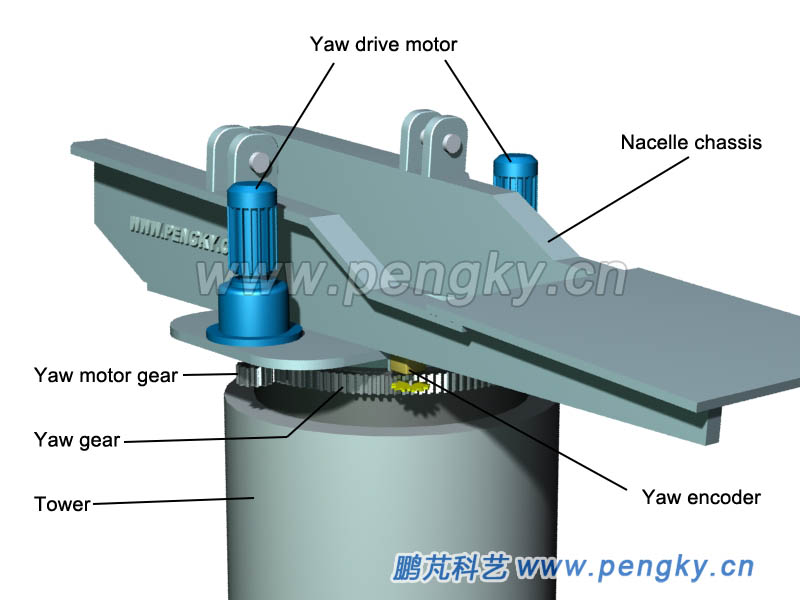
A yaw drive motor is mounted on the chassis of the nacelle, and the pinion is connected through the gearbox of the motor, and the pinion gear meshes with the yaw gear. When the yaw drive motor rotates, the nacelle chassis can be rotated on the tower. There are two to four yaw drive motors, and the number of wind turbines above MW is as high as 6 to 8. Figure 8 is a schematic diagram of a yaw system with two drive motors. The wind direction anemometer transmits the signal to the control cabinet, and after processing by the microprocessor, outputs a control signal, which controls the operation of the yaw drive motor, and starts the yaw drive motor to perform the wind when the wind turbine shaft has a certain deviation from the wind direction. |
||
 |
||
| Figure 8 - Horizontal axis wind turbine yaw system | ||
The generator output cable and signal cable are from the nacelle through the tower to the ground. The small micro wind turbine is equipped with a slip ring device at the yaw shaft. The generator output cable is connected to the cable in the tower through the slip ring. The yaw rotation of the ring will not spoil the cable. For medium and large wind turbine, the output voltage is high, the current is large, the slip ring can't bear, and the generator output cable is connected to the tower distribution box. If the cabin rotates in one direction when it is facing the wind, it will twist the cable. It is necessary to measure the yaw angle to prevent the one-way overturning from twisting the cable. Install the yaw encoder (yaw transducer), the encoder's detection gear is in close mesh with the tower's yaw gear, see Figure 8. When the base rotates, the rotation angle can be measured. The encoder uses an optical coding disc, and a few pulses per revolution and a high precision. When the control system is over-rotated in one direction, it stops, and the reverse yaw rotation is untwisted. Small and medium wind turbine can also use the electromagnetic induction revolution speed transducer to directly count the teeth of the yaw gear to achieve the measurement of the yaw angle. The following is a 3D animation of the yaw system related device operation. |
||
| Animation 2--horizontal axis wind turbine yaw system operation | ||
 |
||
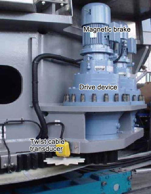
Some small and medium-sized wind turbine use slide bearing for yaw bearings, which can reduce the cost of the yaw system. It will not be introduced here. There is also a brake system for yaw, also called yaw brake. When the wind direction is stable, the yaw motor is not started, and the wind turbine is locked by the brake. Avoid the impact of biased gusts and oscillating winds on yaw devices, make the yaw stable, and brake immediately in case of failure. The brake discs and brake clamps of the yaw brake are all under the yaw bearing. The brake clamps are generally at least two, which are normally closed. The relevant mechanism is not shown here. It is also possible to directly brake the yaw drive motor to achieve yaw brake. Figure 9 is a photograph reprinted from the network in which the white gear under the twisted cable transducer is engaged with the yaw gear. The yaw drive motor has a magnetic brake function. |
||
 |
||
| Figure 9 - Yaw drive motor and anti-twist cable transducer | ||
| Back to Previous Page |
