
| Nacelle Equipment and Tower |
The nacelle is the core of the wind turbine, where the rotating machinery of the wind turbine can be converted into electrical energy. The main equipment in the horizontal axis wind turbine nacelle is the main drive shaft, gearbox, generator, brake apparatus, frame, control equipment, etc. |
| Gearbox |
Due to the high generator speed, the two-pole three-phase alternator rotates at about 3000 rpm, the four-pole three-phase alternator rotates at about 1500 rpm, and the six-pole three-phase alternator rotates at about 1000 rpm, while the wind rotor has a low speed, the speed of the small wind turbine is up to several hundred revolutions per minute, and the speed of the large and medium wind turbine is about tens of revolutions per minute or even ten turns. With such a large difference in speed, the wind turbine can only rotate the generator at the rated speed by increasing the speed of the gearbox, and the speed increase ratio is generally several tens to several hundred times. There are two main types of gear shifting. One is the spur gear shifting, the other is the planetary gear shifting. The gearbox of the wind turbine has a relatively large speed increase. The second-stage planetary gear speed increase or the first-stage planetary gear plus the first-stage spur gear speed increase is adopted. The large speed ratio uses the secondary planetary gear speed increase and the first stage spur gear speed increase. The input and output shafts of the spur gearbox are not on the same axis, and the input and output shafts of the planetary gearbox are on the same axis. The planetary gearbox has a large ratio and a small volume, so the planetary gear speed increase is the most used speed increase method in the wind turbine. The main input shaft of most wind turbine gearbox is tubular, and the central through hole is used for the transmission of signals and power of the hub pitch. Figure 1 is a schematic view of a generator gearbox. |
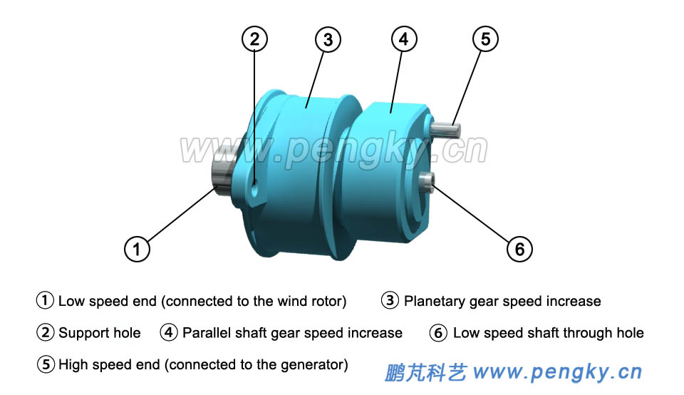 |
| Figure 1 - Wind turbine gearbox |
| Due to the harsh working environment of the wind turbine, the material and process requirements for the gearbox are very high, and the requirements for the lubrication system of the gearbox are also high. For the structure of the gearbox, see the ‘Gearbox for Wind Turbine (1)’ and the ‘Gearbox for wind turbine (2)’. Figure 2 shows the appearance of the gearbox of the wind turbine downloaded from the Internet. There are cooling and lubrication devices. |
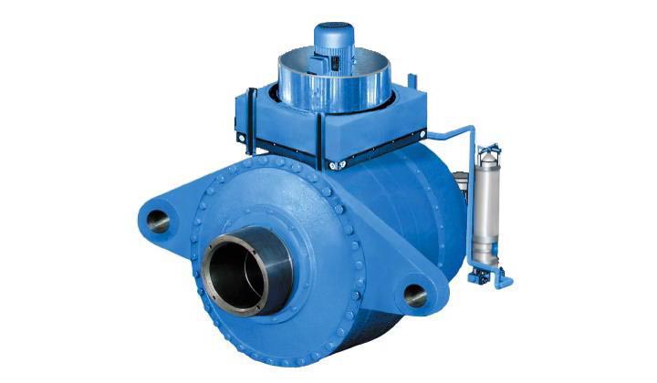 |
| Figure 2 - Gearbox photo |
| Generator |
| Most wind turbine use three-phase alternators, and because of their high efficiency and small size, claw-pole generators are used in miniature and small wind turbines. Depending on the mode of operation, useful synchronous generators are also useful for induction generators. At present, the main operating modes of wind turbines are as follows: |
| Fixed pitch with variable speed |
| The rotor blades are fixed, and the speed of the generator varies with the wind speed. As long as the power can be generated, the wind turbines that operate in small off-grid operation (not connected to the grid) are used more often, and permanent magnet synchronous generators are often used. In most cases, the electricity will be rectified to charge the battery, or inverted into a stable AC power supply. |
| Pitch constant speed |
| The large- and medium-sized wind turbines with variable speed and fixed speed work in the grid-connected state. The frequency of the alternating current required to be issued is 50Hz, and the voltage must be the same as that of the grid. Due to frequent changes in wind speed, the method of controlling the pitch angle is used to control the speed of the wind rotor as stable as possible (only in a small range), using cage-type induction generators to generate electricity, can output a stable 50Hz AC when the generator speed changes little, to achieve direct grid connection. However, the effect of pitch control on the speed of the wind turbine is not ideal. When fixed pitch is running, the wind turbine is often operated in an inefficient state. |
| Variable speed pitch |
In recent years, due to the rapid development of power electronics and computer control, wind power has widely adopted the " Variable speed / constant frequency" mode of operation, the wind rotor is no longer limited to a fixed speed, can be operated in a wide range of speed. The electricity generated by the synchronous generator is rectified and then inverted into a frequency-stabilized alternating current to the grid, so that the wind turbine can work at the highest efficiency. The pitch is mainly used to adjust the generator power when the rated wind speed is exceeded. This is variable speed constant frequency mode. The current popular doubly-fed wind turbines and direct-drive wind turbines are operating in variable speed constant frequency mode. The doubly-fed wind turbine uses a wound rotor induction generator, and the direct drive wind turbine uses a multi-pole permanent magnet generator. There are many ways to control the generator. The content of the generator is beyond the scope of this section. Interested friends should also look for books to read. For the principle and structure of the generator, please go to the “Generator” column and the “Direct Drive Wind Turbine” column. |
| Spindle and hub |
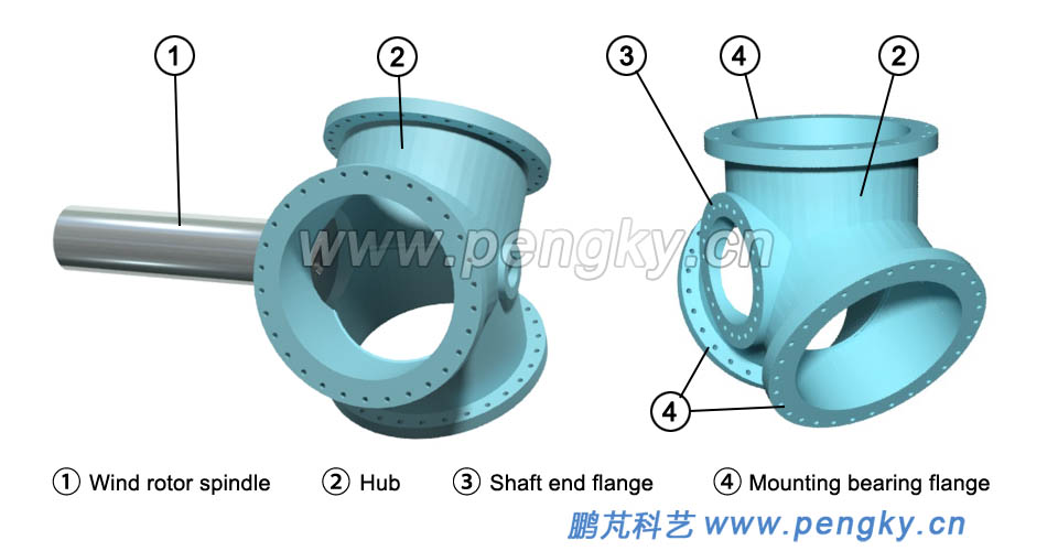
| The gearbox and generator of the wind turbine are installed in the nacelle. The wind rotor is connected to the gearbox through the spindle of the wind turbine. The spindle not only transmits the torque of the wind rotor rotation, but also resists the swing of the wind rotor, and is made of hard stainless steel. The front end of the wind turbine spindle has a hub coupling flange, and the tail end is coupled to the gearbox. The spindle shaft has a through hole, which is the passage of the pitch control cable, oil path or mechanical rod. Figure 3 shows the two types of spindles. |
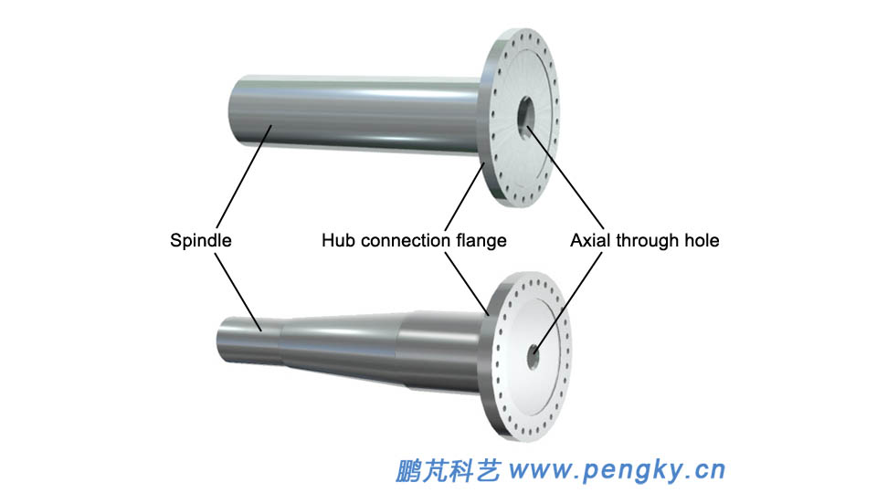 |
| Figure 3 - Wind turbine spindle |
| The hub is a base of the fixed blade, and the blade is mounted on the hub to form a wind rotor, the blade is fixed to the spindle through the hub, and the pitch mechanism of the blade is mounted on the hub. Figure 4 is a spherical hub. Three pitch bearing flanges on the hub can be fitted with three pitch bearings and three blades. The left figure is the outline of the spherical hub, the right figure is the hub mounted on the spindle, and the synchronous pitch drive the mechanism is mounted in a spherical hub. |
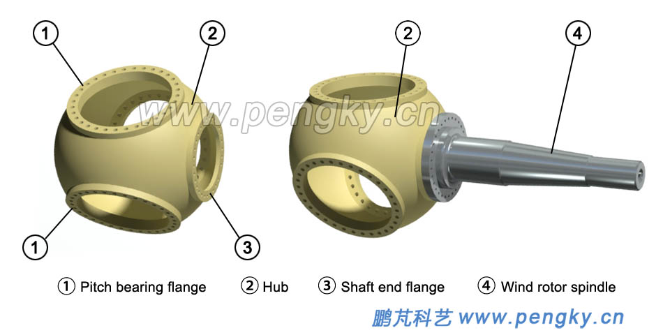 |
| Figure 4 - Spindle and spherical hub |
| Figure 5 is a three-cylindrical hub, also known as a three-pronged hub, which can be fitted with three blades, the right figure is an outline view of a three-cylindrical hub, and the left figure is a hub mounted on the spindle. The pitch bearing of the blade is fixed to the bearing flange for mounting 3 blades. The independent pitch mechanism uses three cylindrical hubs. |
 |
| Figure 5 - Spindle and three cylindrical hubs |
| The spherical hub of figure 6 is fitted with three blades to form a three-blade rotor. A shroud will be installed outside the hub. |
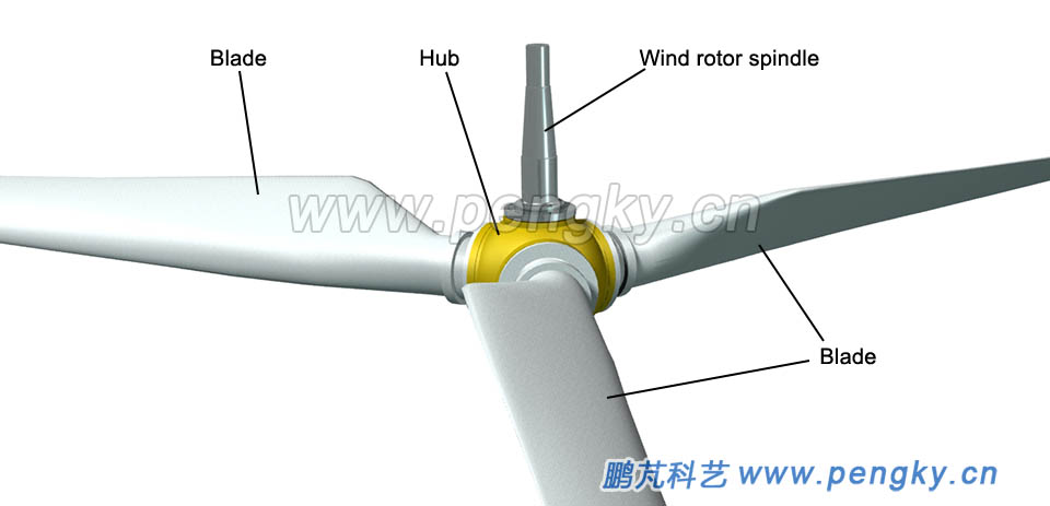 |
| Figure 6 - 3 Blade Wind rotor |
| Main equipment of the nacelle |
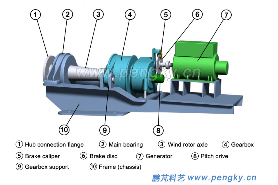
The frame (chassis) consists of beams and longitudinal beams. It is the supporting base for the main equipment such as wind turbines, gearboxes and generators. See figure 7. The spindle of the wind turbine is mounted on the frame of the nacelle through the spindle bearing. The spindle bearing is at the front end of the frame. The spindle bearing is subjected to the huge force from the wind rotor, mainly the weight, thrust and various torsional moments of the wind rotor. The spindle bearing adopts a spherical surface. Roller bearings have good alignment properties. The bearing on the hub is called the front bearing, and the rear end of the spindle is the rear bearing. Figure 7 is a common arrangement. Without the rear bearing, the tail end of the spindle is directly connected to the low-speed shaft of the gearbox through the coupling. |
 |
| Figure 7 - Gearbox, generator, frame |
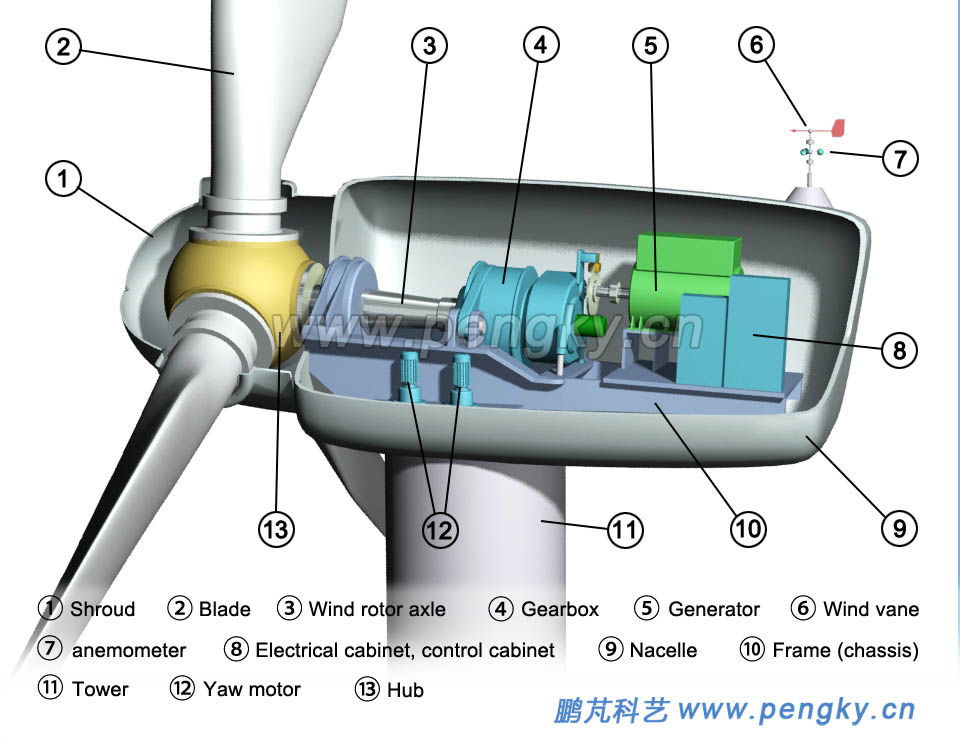
The high-speed shaft on the right side of the gearbox is connected to the generator via a coupling. In order to stop operation during high winds, faults and maintenance, brake discs are mounted on the generator shaft and braked by brake calipers. The spindle through hole of the wind turbine communicates with the low speed shaft through hole of the gearbox, and the signal and power (electric or hydraulic medium) for the wind turbine pitch are transmitted from the rear of the gearbox through the slip ring to the hub pitch device. Or use the connecting rod to directly manipulate the pitch. The axis of the wind turbine spindle is lifted forward and has a small angle with the horizontal line. The purpose is to prevent the blade from hitting the tower and shorten the extension length of the wind turbine spindle. A lubrication system for the gearbox is also installed in the nacelle to ensure lubrication of the gearbox; large generators also have a dedicated cooling system. There is a yaw system under the nacelle base, and a wind vane and anemometer are installed at the top of the nacelle to output its signal to the control cabinet. The yaw device pushes the wind turbine against the wind according to the signal of the control cabinet. The control cabinet also controls the pitch angle according to the change in wind speed to work at the optimum speed. Figure 8 is a layout view of the equipment in the nacelle of the horizontal axis wind turbine. |
 |
| Figure 8 - Wind turbine nacelle structure and equipment layout |
| For direct-drive wind turbines, there are no gearboxes. For the composition and construction, see the "Direct Drive Horizontal Axis Wind Turbine" courseware. |
| Tower |
The rotor must obtain a relatively stable wind at a certain height. The wind turbine and the nacelle in the air should be supported by the tower. The height of the tower is about 1 to 1.5 times the diameter of the rotor. The tower of the small micro wind turbine Relative to the wind rotor will be higher. The tower needs high strength and also considers the cost. The micro wind turbine is the iron pipe and the cable. The small and medium-sized wind turbines are of the truss type and the pipe type. The large wind turbines basically adopt the pipe type. The truss is made of angle steel and other profiles. It is simple and low in cost, but it is not beautiful and the people are not safe. The tubular column of large wind turbines mainly adopts reinforced concrete structure or steel structure, but the steel tower is difficult to transport, and the concrete towers that can be produced on site are used more and more. The power cable and control signal cable of the generator are placed in the tower. The tower has a tower door at the bottom. The tower is divided into several layers. There are straight ladders between the floors to facilitate the up and down of the personnel. See figure 9. |
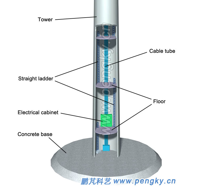 |
| Figure 9 - Shows the internal structure of the tower |
| Figure 10 is an internal picture of the tower reproduced from the network. |
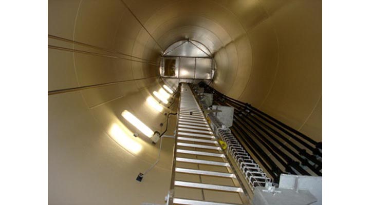 |
| Figure 10 - Inside photo of the tower |
| Back to Previous Page |
