Working principle and structure of horizontal axis wind turbine
Working principle of horizontal axis wind turbine
Toy windmill with thin blades
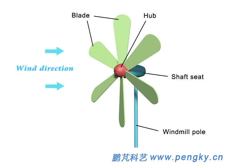
The rotor axis of the horizontal axis wind turbine is horizontal, and the ground is substantially parallel to the wind direction. Figure 1 is a toy windmill with a shaft seat fixed to the windmill pole and a hub in front of the shaft seat. The two are connected by a windmill shaft, and the hub is free to rotate around the windmill shaft. The windmill has six blades, the blades are fixed on the hub, the blades are perpendicular to the windmill shaft, the angle between the blades is 60 degrees, and the six blades and the hub form a wind rotor, each blade having 25 degrees with respect to the plane of the wind rotor (or Angle of inclination of a similar angle). When the wind shaft is parallel to the incoming wind, the wind rotor will rotate.
Figure 1 - Toy Windmill
Let's talk about the principle of small windmill rotation. In the wind turbine basic courseware, the force of the thin plate in the flowing air is introduced. When the thin plate has an angle with the airflow direction, the thin plate obtains lift and resistance under the action of the airflow.
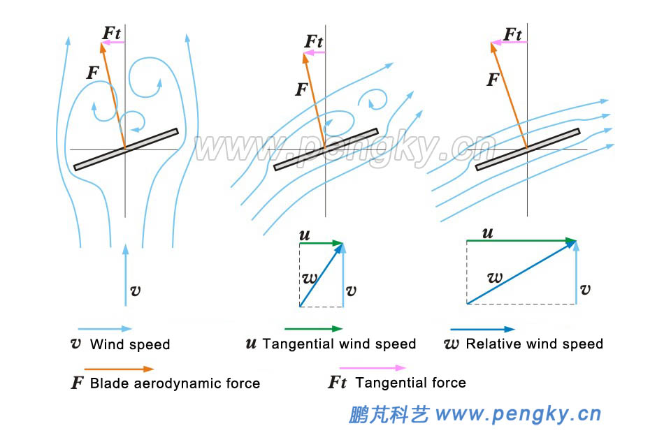
Figure 2 is a schematic view of the force of the thin blade of the windmill at different rotational speeds. In the figure, the thin plate is a section of the blade on a certain circumference of the wind rotor. In the figure, the rotating shaft of the wind rotor is perpendicular to the picture, so the moving direction of the blade is horizontal with respect to the picture. The direction of the incoming wind is upward relative to the picture, and the wind speed is v.
The left picture of Figure 2 shows the airflow condition when the windmill has not been rotated. At this time, the airflow bypasses both sides of the thin blade and forms a vortex behind the blade. The front of the blade (relative to the picture is below) has a large pressure difference from the rear, due to the blade is not perpendicular to the wind direction, and the pressure difference force F generated by the airflow on the blade has an angle with the rotating shaft of the wind rotor. This angle causes F to generate a component force Ft in the moving direction of the blade, and Ft is tangent to the circumference of the wind rotor here, pushing the blade Turn to the left, so the windmill starts to rotate, and Ft is also called tangential force.
Figure 2 is a picture showing the state of the airflow when the windmill is rotated at a medium speed. At this time, the wind speed is still v. Since the windmill has been rotated, the linear velocity at the section of the thin blade is u, and the direction is to the left, so that the blade receives the wind. In addition to the air flow u from the left, the combined wind speed of v and u is w, see the vector synthesis picture below, and the relative wind speed w is the true wind direction that the thin blade receives. The upper part of the figure shows the airflow state of the blade at this time. Since the direction of the incoming wind w has a large angle with the blade, see the angle between w and the upper blade in the lower vector picture. When the airflow flows through the blade, it is generated behind the blade. The eddy current, the blade works in the stall state, although there is a certain lift, but the resistance is also large, the combined force is F, F produces the component force Ft in the direction of the blade movement, and Ft pushes the blade to the left.
Figure 2 - Schematic picture of the force of the windmill thin blade at different speeds
The right picture of Fig. 2 is the airflow state when the windmill rotates at high speed. At this time, the wind speed is still v. Since the speed u is high, the angle between the synthetic airflow w and the blade (angle of attack) is small, see the vector below. The angle between w and the upper blade. At this time, the blade obtains a large lift, the resistance is small, and the component force Ft of the resultant force F is large, and the blade is driven to rotate at a high speed.
Dutch windmill with thin blades
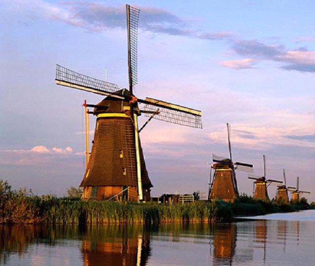
Wind turbines with thin blades such as small windmills have long been used, typically Dutch windmills. As early as the 13th century, Dutch people used wind turbines to pump water, grind grain, and process barley. At the end of the eighteenth century, there were about 12,000 windmills in the Netherlands. The towering pumping windmills made the Netherlands obtain nearly one-third of the land from the sea. This is a great miracle created by ancient wind turbine applications. This is also due to the fact that the Netherlands is full of west winds throughout the year. Later, the invention and application of steam engines, internal combustion engines and electric motors gradually eliminated most of the windmills. At present, there are more than 2,000 windmills in the Netherlands. Due to the use of natural wind and no pollution, many of them are still functioning. Figure 3 is a photograph of a Dutch windmill on the network.
Figure 3 - Dutch windmill
Below is an animation of a Dutch windmill.
Dutch windmill animation
The blades of the toy windmill are thin plates, and the blades of the Dutch windmill are tight canvases (the windmill blade skeleton is not stretched on canvas in Fig. 3), and the blades are all flat. The shaft of the windmill is basically parallel to the ground, so it is also a horizontal axis wind turbine.
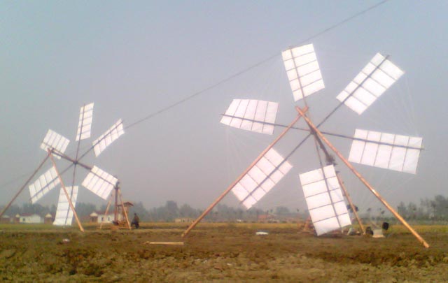
In fact, in the Han Dynasty of China, there were horizontal axis wind turbines. These windmills were called horizontal windmills or inclined pole windmills.
Figure 4 is a representation of two horizontal shaft windmills.
Figure 4 - China's early horizontal windmill replica
Airfoil shaped blade
The thin blade has a small stall angle and is easy to enter the stall state. The blade of the modern practical application is streamline, and the blade section is like a wing section, which is called an airfoil. The airfoil has a certain thickness, high strength, large lift and low resistance. See the aerodynamic basic courseware for the blade for an introduction to the airfoil.
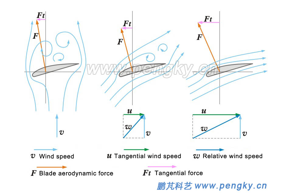
Figure 5 is a schematic view of the force of the airfoil shaped blade at different rotational speeds. In the figure, the plate is a section of the blade on a certain circumference of the wind rotor. In the figure, the rotating shaft of the wind rotor is perpendicular to the picture, so the moving direction of the blade is horizontal with respect to the picture. The direction of the incoming wind is upward relative to the picture, and the wind speed is v.
There are three working states in the figure. The left picture shows the state when the wind rotor is stationary. The middle picture shows the state when the wind rotor rotates at a low speed. The right picture shows the state when the wind rotor rotates at the rated speed. The airflow and force analysis conditions of the three states are basically the same as those of the thin plate of Fig. 2, and will not be repeatedly described here.
Figure 5 - Schematic picture of force of airfoil blades at different
Looking at the working efficiency of a wind turbine is not just looking at the tangential force Ft of the blade. In Figure 4, the Ft on the right is about twice the Ft of the middle image. Is the output power 2 times larger? We have to look at them. The rotational speed, the tangential velocity u on the right is about 2.5 times that of the middle figure u, that is, the rotational speed is 2.5 times larger, so the blade on the right is 5 times more powerful than the middle blade (2 × 2.5 = 5). This is only a rough number, because the cross-section and angle of the different parts of the wind rotor are different, and the wind is different.
This kind of wind turbine is driven by the lift of the blade to push the rotor to rotate, also known as the lift wind turbine.
The composition and form of the horizontal axis wind turbine
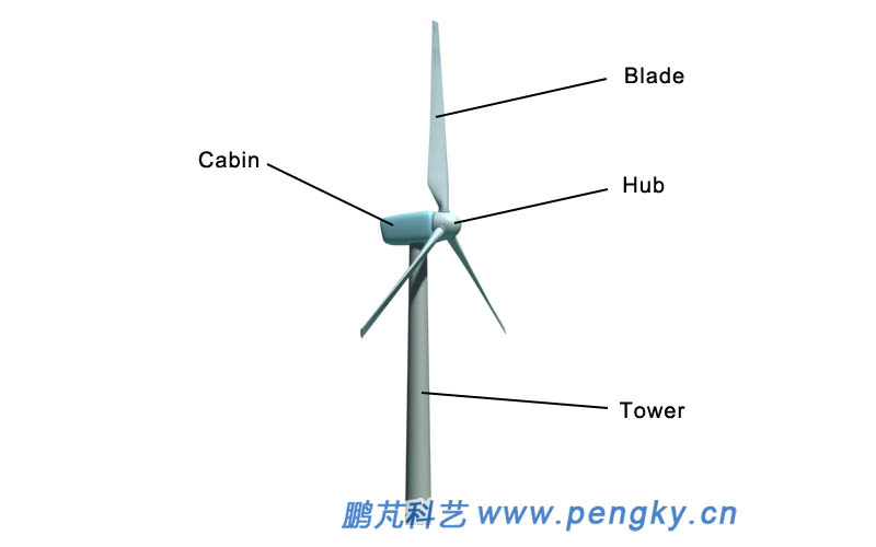
Most modern wind turbines are horizontal-axis wind turbines, and horizontal-axis wind turbines are mainly composed of blades and hubs, nacelles and towers. A common wind turbine has three blades. The blades are mounted on the hub to form a wind rotor. The wind blower rotates the generator in the engine compartment to generate electricity. The tower is the support of the entire wind turbine, as shown in Fig. 6.
Figure 6 - Composition of the horizontal axis wind turbine
Number of blades of the wind turbine
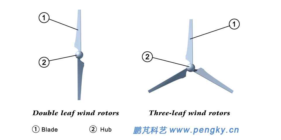
In addition to the three blades, the wind rotor has two blades, even single blades, as shown in Figure 7.
Figure 7 - Double-blade and three-blade
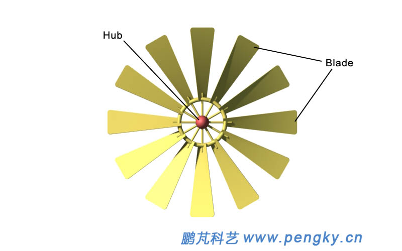
There are also 4 leaves, 5 leaves, 6 leaves, and many wind turbines are used in many agricultural wind turbines, see Figure 7.
Figure 8 - Multi-blade wind rotors
Please use the "Wind Rotor Solidity" courseware to watch how many blades are suitable.
Wind turbine form
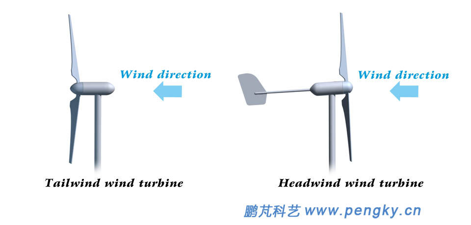
The wind rotor should face the wind direction to receive the best wind energy. Facing the wind direction, the wind rotor is called the windward wind turbine in front of the tower. The wind rotor is called the tailwind wind turbine in the leeward direction of the tower. See Figure 9.
Figure 9 - Windward wind turbine and tailwind wind turbine
Making the wind turbine automatically toward the wind direction is called the wind (yaw) function. Small wind turbines generally use the tail rudder to wind, and the wind blows the tail rudder to the wind turbine to make the wind rotor face the wind. The windward wind turbine in Fig. 8 is the wind turbine with the tail rudder. The downwind wind turbine can automatically wind against the wind without any device, which is called free yaw. Large and medium-sized wind turbines use a special yaw device for wind, which is described in later chapters.
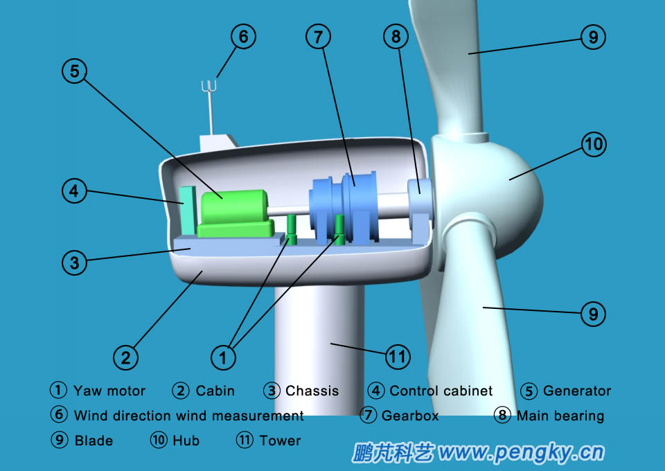
Main equipment in the cabin
The main bearing, the gear box, the generator, the yaw device, the wind direction wind speed measurement, the control cabinet, etc. are installed on the cabin chassis of the wind turbine generator, and the generator is a device for generating electric energy by the wind turbine, and the wind rotor is high due to the high speed of the generator. The speed is low, the wind rotor needs to increase the speed through the gear box to make the generator work at the normal speed; the control cabinet controls the wind speed and the wind rotor speed of the wind turbine; the wind direction measurement wind direction sends a signal to the control cabinet; the yaw device presses the control cabinet the signal drives the wind turbine to perform the wind.
Figure 10 - Schematic picture of the main equipment in the engine room
A plurality of wind turbines form a wind farm. The video of the Xinjiang Da Ban Cheng Wind Farm shows the grandeur of the wind farm. The video is only the corner of the Da Ban Cheng Wind Farm.
A corner of the Da Ban Cheng Wind Farm in Xinjiang, China