| |
| Three-phase AC motor winding |
| The basics of AC motor windings are introduced in the "AC Motor Winding" courseware, and the windings of single-phase motors are introduced. The windings of three-phase AC motors are introduced in this courseware. |
| Three-phase AC motor winding basic structure |
It is well known that both electromotive force induced in the three-phase AC motor produces and rotating magnetic field generated on the three-phase AC generator are from an important part of the motor or generator, that is, the windings.
The basic requirement for three-phase AC motor windings is:
The potential waveform generated by the three-phase AC motor and the magnetic field of the three-phase AC motor must be close to a sine wave and achieve the required amplitude.
The potential or magnetic field generated by the three-phase windings must be symmetrical, and the resistance and reactance of each winding should be balanced.
The copper loss of the winding is small, and the same to the amount of copper.
Its Insulation should be reliable, there is need for high mechanical strength, dissipate sink heat, and simple manufacture.
The specific windings in a three-phase AC motor are mainly based on the following data:
P Magnetic pole pairs
For the motor with P pairs of magnetic poles, the number of magnetic poles is 2p. For example, one magnetic pole pair motors produces a rotating magnetic field in 3000 rpm with three-phase AC of 50 Hz, and two magnetic pole pairs motors produces a rotating magnetic field in 1500 rpm .
Pole τ
The width of each pole (measuring through the number of slots),
τ=Z/2p Z is the total number of slots of the stator,
Phase band q
The width of each phase under each pole (measuring through the number of slots),
q = Z / 2pm m is the number of phases
For example, for a three-phase motor with a total number of slots of 24 and two magnetic pole pairs, the pole pitch is 6 and the phase band is 2.
The application of phase-band division to design windings is a basic method which is simple and easy. The main steps are:
1. First determine the number of phases of the motor, the number of poles of the motor, and the form of the winding
2. Draw a circle diagram with all the slots
3. Calculate the number of slots in each pole and phase
4. Calculate pole pitch and pitch
5. Division phase
6. Connect the ends to form the coil
7. Connect the coils to form the winding
For, some other methods is needed for other complicated windings. The following is an example for analyzing two three-phase motors by the phase band division way. |
| Three-phase AC motor windings |
| 2-pole 6-slot single-layer three-phase winding |
The simplest is the three-phase winding with 2 poles and 6 slots, which is the most basic winding mode in the "three-phase AC motor principle model" courseware. Its pole pitch is 3 and the phase band width is 1.
Set the 1, 2, and 3 slots is N poles, and set the 4, 5, and 6 slots is S poles (the poles here are not the north and south poles of the specific magnetic field), and there are 3 phase bands under each pole, slots under each phase band connect as one coil, wand the winding directions of each neighboring phase bands are reversed. See figure 1, the light blue coil is single U-phase winding, the green coil is single V-phase winding, and the red coil is single W-phase winding. |
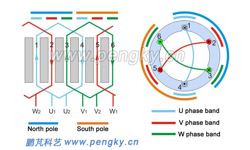 |
| Figure 1 -- 2 pole 6-slot single-layer chain expand winding |
| 2 poles and 12 slots single-layer chain three-phase winding |
The core utilization of the 6-slot motor is too low and is just only used to explain the principle. 12 slots is applicable at least for three-phase motor... The following describes a single-layer chain winding with 2 poles and 12 slots of three-phase motor.
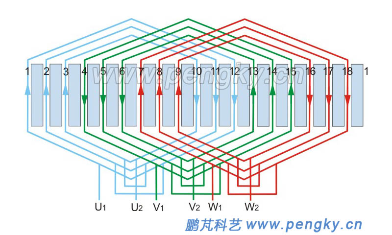
A simple calculation shows the pole pitch is 6 and phase band width is 2. Figure 2 is a circular diagram of a 2-pole 12-slot three-phase motor with 2 poles and 12 slots, setting 1 to 6 slots as N poles, and 7 to 12 slots as S poles.
There are 3 phase bands U, V and W under the N and S poles, connect the slots in the same phase band under each N pole and the S pole into a coil. Slot 1 and 8 consist a coil, slot 1 is a first end, slot 2 and 7 consist a coil, slot 2 is a first end, and the two coils are connected end to end to form U-phase winding, so that the effective sides of the same winding are under the same polarity. The winding directions are the same (the current direction is the same), and the winding directions under the opposite magnetic poles are opposite. The same connecting way is to V-phase winding and W-phase winding. I
The coils of neighboring phase bands are wound in opposite directions, seeing figure 2.
The power supply lead wires of each phase winding should be separated by an electrical angle of 120°. For 2-pole motor, the electrical angle is the same as the mechanical angle, both of them is 120 °. Select 2 slots as U1 end, select 10 slots as V1 end, and select 6 slots as W1 end; then the 8 slots is for U2 end, 4 slots is for V2 end, and 12 slots is for W2 end. |
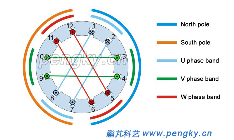 |
| Figure 2 -- 2poles and 12 slots single-layer chain winding |
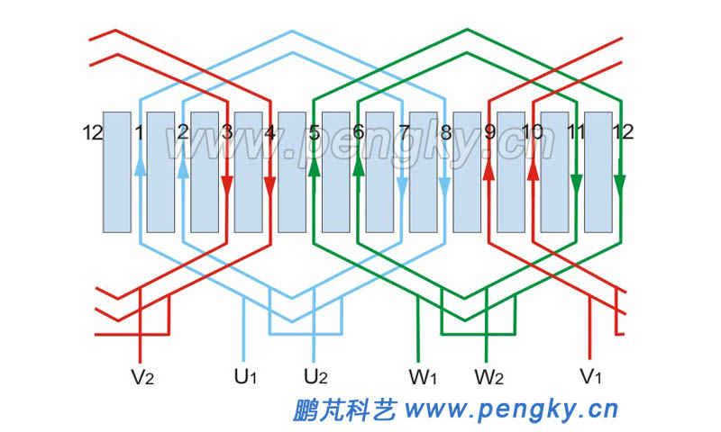
| Figure 3 is single-layer chain winding expansion drawing with 2 poles and 12 slots. In the figure, the light blue coil is U-phase winding, the green coil is V-phase winding, and the red coil is W-phase winding. |

| Figure 3 -- 2-pole 12-slot single-layer chain winding development |
In the "three-phase AC motor model" courseware, there are a stereogram diagram of 2-pole 12-slot single-layer chain windings and a schematic diagram of the winding down-line process with animation.
Some expansion drawing of three-phase windings will be only introduced later without and analysis. |
| 2-pole 12-slot single-layer concentric three-phase winding |
 |
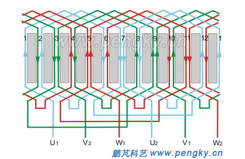
| Figure 4 -- 2-pole 12-slot single-layer concentric three-phase winding |
| 2-pole 18-slot single-layer cross three-phase winding |
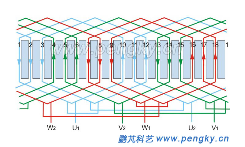 |
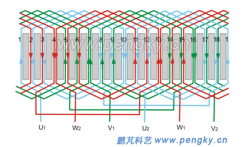
| Figure 5 -- 2-pole 18-slot single-layer cross three-phase winding |
| 2-pole 18-slot single-layer concentric cross winding |
 |
| Figure 6 -- 2-pole 18-slot single-layer concentric cross winding |
| 2-pole 12-slot double-layered stack winding around three-phase winding |
| To simplify complex graphics, the coils in the double-layered winding are represented by a single frame. |
 |
| Figure 7 -- 2-pole 12-slot double-layered stack winding around three-phase winding |
| 2-pole 18-slot double-layered stack winding around three-phase winding |
 |
| Figure 8 -- 2-pole 18-slot double-layered stack winding around three-phase winding |
| 4-pole 24-slot double-layered stack winding around three-phase winding |
 |
|
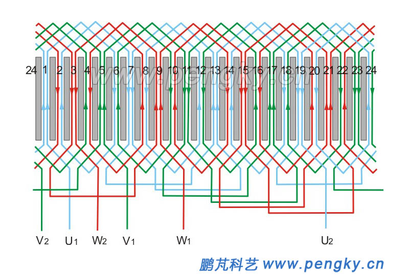
Figure 9 -- 4-pole 24-slot double-layered stack winding around three-phase winding |
|
| Connection of three-phase AC motor windings |
| Three-phase AC motor generally leads the six ends including first and end terminal of the three windings into the junction box of the casing and is connected to the six terminals. They are connected with each other in the junction box and connect to the external three-phase power supply. Star and triangle type are main connection way. |
| Star connection |
| Star connection is also referred to as Y-connection, and the left diagram of figure 10 is a star connection of three windings, with a spiral coil representing the winding. The figure on the right is the terminal block in the junction box. There are 6 terminals on the board, W2, U2, V2, U1, V1, W1, Connect W2,U2 and V2 with shorting tabs (the connection point is called neutral line N), U1, V1, and W1 are respectively connected to the three-phase power supply of the outside A, B, and C. |
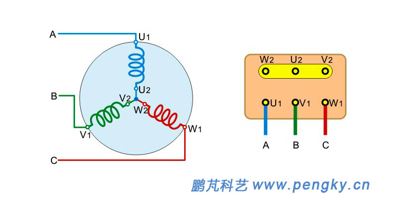 |
| Figure 10 -- Three-phase winding star connection |
| Triangle connection |
| The triangle connection is also called the Δ-connection. The left diagram of figure 11 is the triangle connection of the three windings. The right diagram is the terminal block in the junction box. There are six terminals on the board, W2, U2, V2, U1, V1, and W1. Connect W2 and U1 with shorting tabs and use them as the A-phase power input terminal; connect U2 and V1 with shorting tabs and use as B-phase power input terminal; use V2 and W1 shorting tabs connected and used as an off-board C-phase power input. |
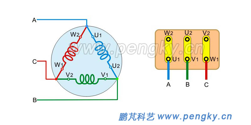 |
| Figure 11 -- Three-phase winding triangle connection |
The specific connection method should be connected according to the connection method marked on the motor nameplate.
Most three-phase AC motors use triangle connection, but some motor names are marked with "voltage 380V/220V" and "connection Y/Δ", which indicates that the Y-connection is applied for the line voltage of the power supply is 380V; while the line voltage of the power supply is 220V, Δ-connection is selected.
Three-phase asynchronous motor with large power has a large starting current. In order to avoid excessive impact to power grid, the “Y-Δ” starting is adopted, Y-connection is at start-up, the starting current will be small, as motor speed is close to the rated speed. Then change to Δ-connection.
Three-phase AC motors are usually taken out of the machine through star connection. |
| |
|

