
Three Phase Alternator Model |
This courseware introduces a popular generator model that can send three-phase alternating current, the model is three-phase alternator with 2 poles and 12 slots, and the structure is close to the real three-phase alternator. Figure 1 is the stator core of the model, which is laminated from stamped silicon steel sheets. The inner circumference of the stator core has a groove in which the stator coil is embedded, the grooves are called teeth. |
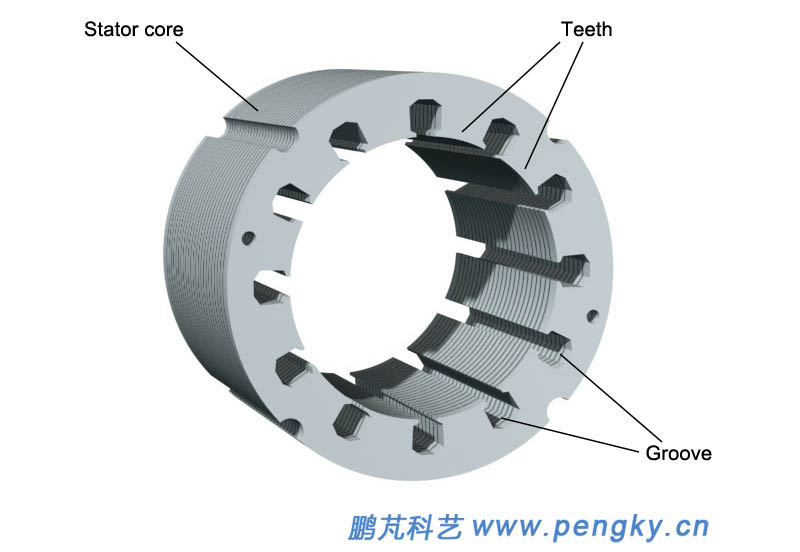 |
| Figure 1—Stator core |
| The stator core is pressed by the stator core pressing ring and the pressing screw, as shown in figure 2. |
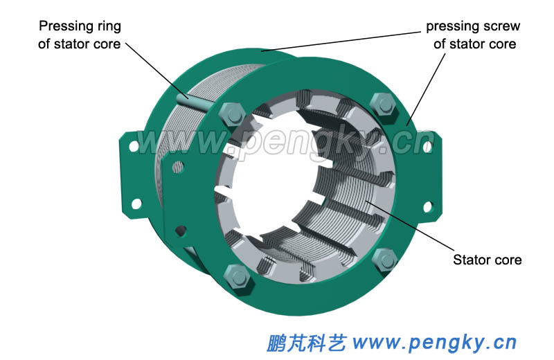 |
| Figure 2 -- Compacted stator core |
Inserting the stator three-phase winding into the slot of the stator core, for showing the windings of each phase clearly, the A-phase winding is shown in light blue; the B-phase winding is shown in green; the C-phase winding is shown in red, seeing figure 3. The order of the installing wire of the stator coil is further introduced in figure 11 to figure 15. |
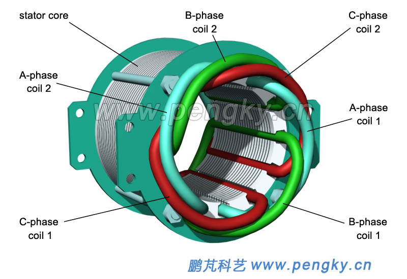 |
| Figure 3—Stator core and windings |
| Rotor core with 2 poles is made of magnetically permeable steel and mounted on the rotor shaft. |
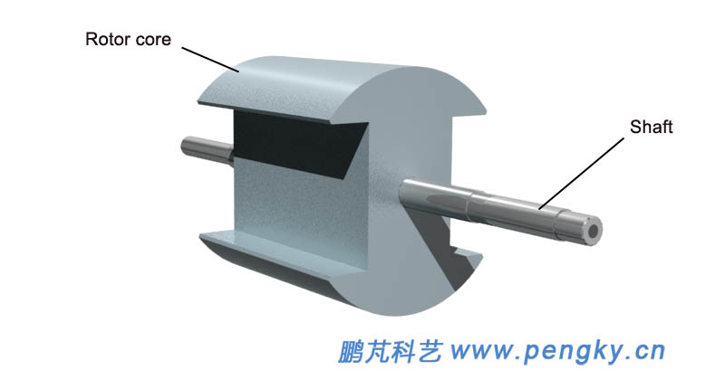 |
| Figure 4—Rotor core with 2 poles |
| Install the coil frame on the rotor core and wind the excitation coil, then install a slip ring on the shaft, and connect the two wire ends of the excitation coil to the two slip rings, as shown in figure 5. See the common generator model for the structure and installation method of the coil frame. |
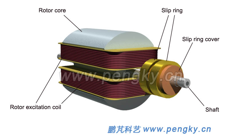 |
| Figure 5—Rotor core and excitation coil |
| Figure 6 is a view showing a state in which a rotor is inserted into a stator. |
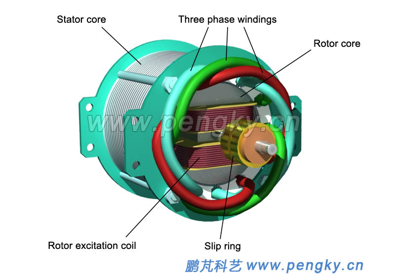 |
| Figure 6—Stator and rotor |
| The bearing of the rotor shaft is mounted on the front bearing frame and the rear bearing frame; the bearing frame is mounted on the stator core pressing ring; there are four legs fixed on the stator core pressing ring, and the generator is mounted on the bottom plate through the supporting legs, as shown in figure 7. |
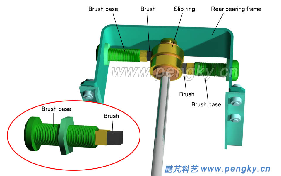 |
| Figure 8—Installation brush |
| The assembled generator model is shown in figure 9. |
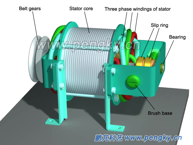 |
| Figure 9-- Three phase Alternator model |
| Install the terminal block on the generator base plate, which is equipped with 6 terminal posts, 4 terminal posts is for the output connection between the three-phase AC wire and the neutral wire, and the stator windings are connected by a star to lead the neutral wire. The rotor excitation coil is powered by a brush and led to the other two terminals. The entire generator model is shown in figure 10. |
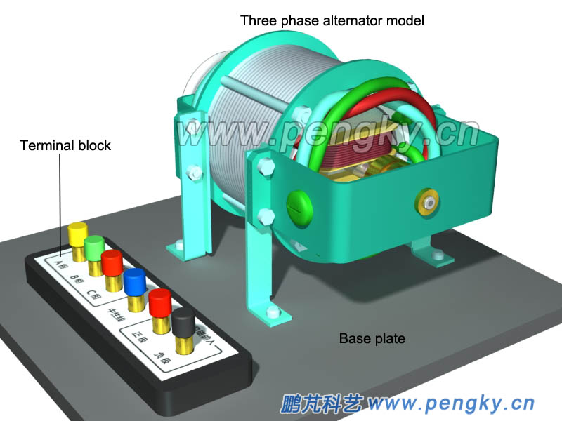 |
| Figure 10—Three phase alternator model and connection terminal block |
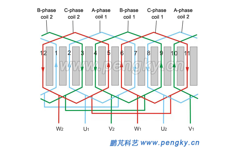
| The electronic winding of this generator model is introduced below, this is a three-phase alternator with 2 poles 12 slots, the winding development diagram is shown in figure 11,which is a single-layer chain winding method, and introduced in the three-phase AC motor winding courseware. This courseware only introduces the specific winding arrangement. |
 |
| Figure 11—Generator winding expand diagram |
| For the convenience of viewing, the stator core pressing ring is omitted, and the slot number is marked on the side of the slot for the convenience of the embedding line. When the A-phase coil 1 is embedded, one side is embedded in the No. 7 slot, and the other side is first suspended to facilitate the embedding of the rear coil, and finally place in the 2 slots, as shown in figure 12. |
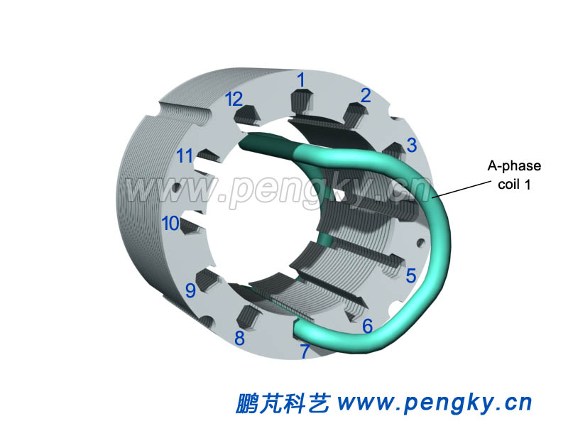 |
| Figure 12 –Embedding A-phase coil |
| When B-phase coil 1 is embedded, one side is embedded in the No. 9 slot, and the other side is first suspended to facilitate the embedding of the rear coil, and finally place in the 4 slots, as shown in figure 13. |
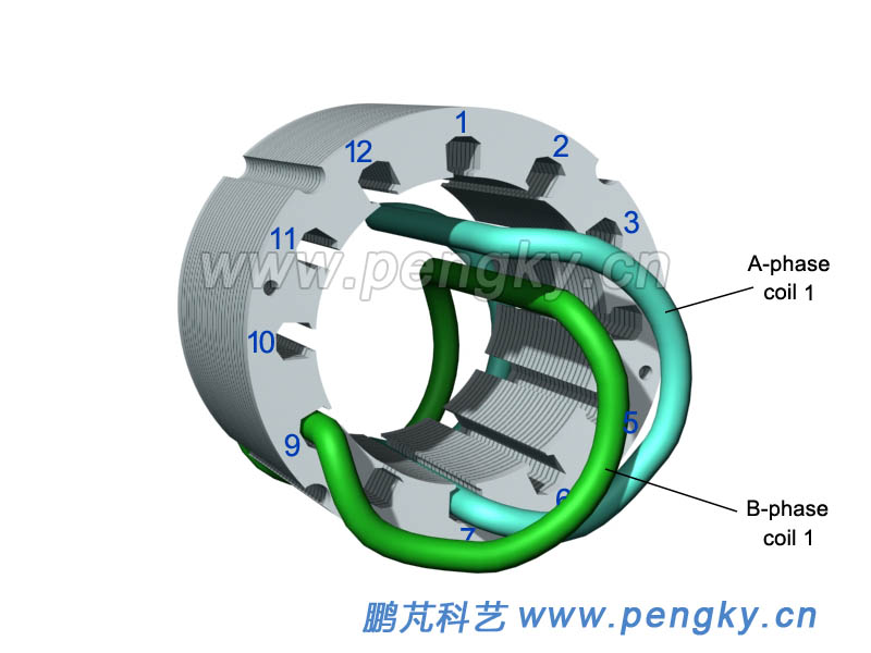 |
| Figure 13-- Embedding B-phase coil |
| Insert the C-phase coil 1 with one side embedded in slot 6 and the other side embedded in slot 11, see figure 14. |
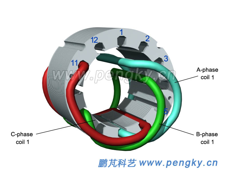 |
| Figure 14-- Embedding C-phase coil |
| While inserting the A-phase coil 2, insert one side into the No. 8 slot, and the other side into the No. 1 slot. As Inserting the B-phase coil 2, insert one side into the No. 10 slot, and the other side into in slot 3 through the A-phase coil 1. When embedding C-phase coil 2, one side is embedded in slot 12, the other side is embedded in slot 5 passed through phase A coil 1 and phase B coil 1. See figure 15. |
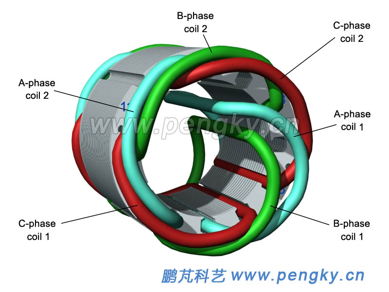 |
| Figure 15-- Embedding three coils remaining |
The other side of the A-phase coil 1 and the B-phase coil 1 are respectively placed back into the No. 2 slot and the No. 4 slot, and the operation of installation line is completed. Figure 16 is a diagram of a stator core and a winding.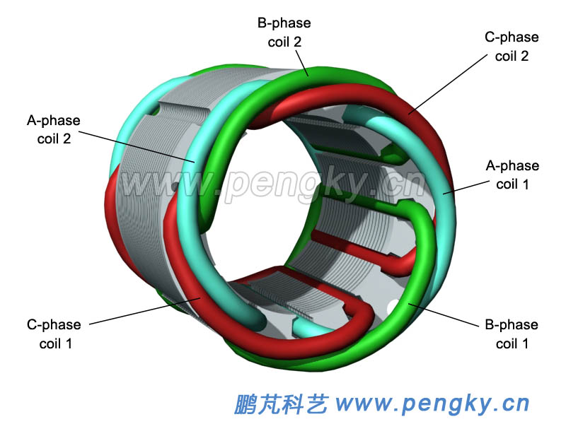 |
| Figure 16—Stator core and windings |
| The embedding process described above is demonstrated in the animation below. |
| Embedding process of three phase motor |
 |
According to figure 11, the two coils of the A phase are connected to form the A phase winding, then take out the U1 end and the U2 end; the two coils of the B phase are connected to form the B phase winding, and the V1 end and the V2 end are taken out; the coils are connected to form a C-phase winding and lead to the W1 and W2 terminals. The three windings are connected in a star shape to lead out the neutral line. Since the three-phase generator model is a 2-poles type generator, if it is to emit alternating current of 50 cycles per second, it must have a rotational speed of 3000 revolutions per minute, with a small asynchronous motor and the same speed, it can emit AC power in three phases of less than 50 cycle, Through the pulley speed increase transmission, slightly amplify the transmission ratio, can send three-phase alternating current of about 50 cycles. |
| Back to Previous Page |
