
| Alternator Principle |
According to the principle of electromagnetic induction, when the wire is subjected to the movement of the cutting magnetic field line in the stable magnetic field, the electrons in the moving conductor are subjected to the Lorentz force to generate an electric potential at both ends of the wire, and the potential direction follows the right-hand rule, and the generated potential is called motional electromotive force. The generator is based on this principle to generate electricity. The following is a schematic model to demonstrate the working principle of the generator. In figure 1 below, there is a pair of magnets used to generator the magnetic field of the generator with magnetic lines from North Pole to South Pole. Note: for simplicity and clarity, the closed magnetic circuit is not shown in this figure, only the magnetic field generating the potential portion. A rectangular coil is placed in the magnetic field, and both ends of the coil lead to two slip rings, which is connected to the output line through a brush, meanwhile a load resistor is connected to the output line end showing in figure 1. |
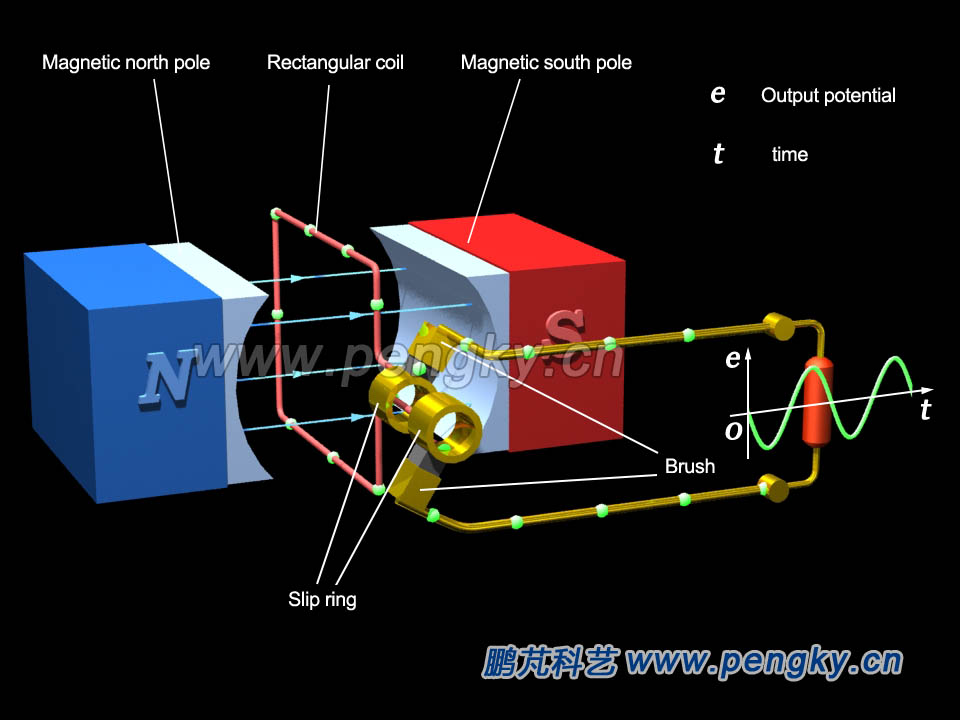 |
| Figure 1-- Alternator Principle |
According to the principle of electromagnetic induction, when the coil rotates, the induced electromotive force will be generated at both ends of the coil. As the magnetic field is uniform and the rectangular coil rotates at a constant speed, the induced potential varies sinusoidal, and sinusoidal alternating current passes through the load resistor, so is a single-phase alternator principle model shown. The following is an animation to demonstrate the working process. The direction of the green ball movement in the animation indicates the direction of the induced current and the speed of the motion indicates the magnitude of the induced current. Watch a 3D animation that explains how this alternator model works. |
| Single-phase alternator principle model in 3D animation |
 |
| The potential induced by a single wireframe is too weak, and multiple windings can be used instead of a single wireframe to generate a higher potential. The potential is n times the single frame, and n is the number of turns. |
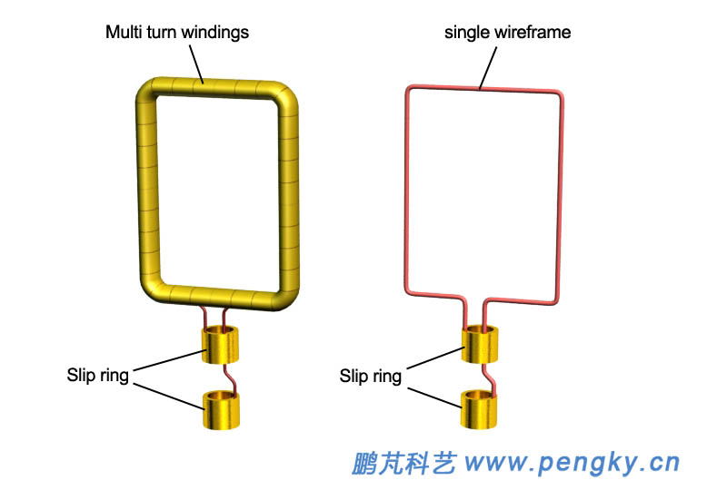 |
| Figure 2--Multi-turn windings and a single wireframe |
| Figure 3 is a single phase alternator model with multi-turn windings |
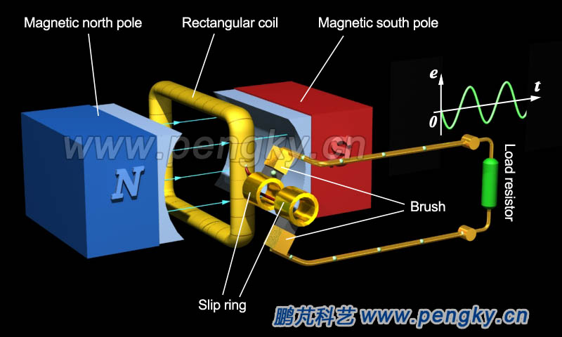 |
| Figure 3—Single phase alternator principle model with multi-turn windings |
| The following is a demonstration animation of single-phase alternator principle model with multi-turns winding |
| Single-phase alternator principle model animation with multi-turn winding |
|
| The truly usable single-phase alternator model is described in the “Single-Phase Permanent Magnet Alternator Model” courseware. |
| Back to Previous Page |
