
| Principle of Transverse Flux Permanent Magnet Generator | |
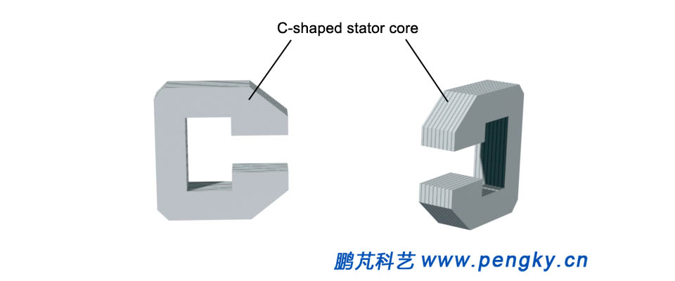
The transverse flux motor is a new type of motor. A brief introduction to the transverse flux in the Structure and classification of permanent magnet motor has been done.The basic form of Transverse flux machine is introduced in this section. The model is simple in structure and can explain Principle of Transverse flux permanent magnet generator. Transverse flux permanent magnet generator usually consist of multiple core components. Fig. 1 is two stator components. The components are formed by stacking C-shaped silicon steel plates. They are called C-shaped stator cores. The middle space of the C-shaped stator core is where the stator coil passes, and the nick of the C-shaped stator core is where the rotor pole passes. |
|
 |
|
| Figure 1 C-shaped stator core | |
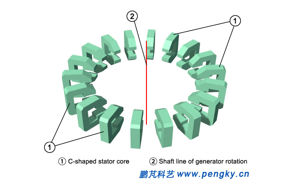
The entire stator core is composed of a plurality of C-shaped stator cores arranged around the axis of the motor shaft. Figure 2 shows that the nick faces the central axis. |
|
 |
|
| 1- C-shaped stator core 2- Motor shaft axis | |
| Figure 2 Arrangement of stator cores | |
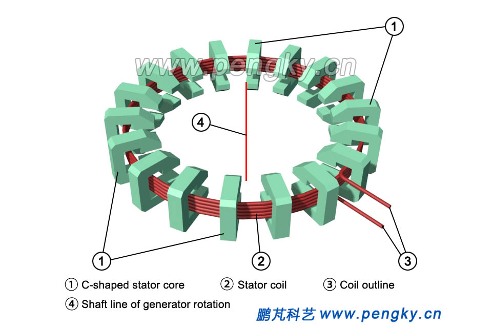
The stator coil is a circular coil centered on the axis of the motor shaft.The coil passes through the middle of the C-shaped stator core, as shown in Fig. 3. |
|
 |
|
| 1- C-shaped stator core 2- Stator coil 3- Coil outlet 4- Motor shaft axis | |
| Figure 3 Stator core and stator coil | |
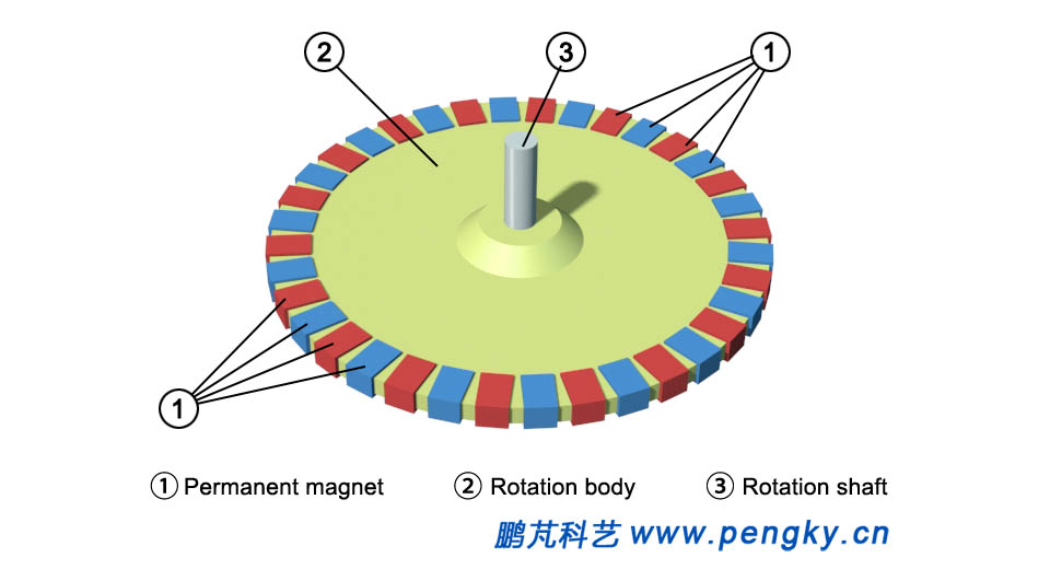
The rotor of the transverse flux permanent magnet generator is composed of a permanent magnet pole and a rotor body. The rotor body is a support body of the rotor and has a disk shape. The outer edge portion of the rotor body mounted permanent magnet is made of a non-magnetic material. The number of permanent magnets used as magnetic poles is twice that of C-shaped stator cores. The section of magnetic poles is the same as that of C-shaped stator cores. The magnetic poles of permanent magnets are evenly arranged on the outer circumference of the rotor. There is a gap between the permanent magnets. The through direction is parallel to the motor shaft. The adjacent permanent magnets have opposite magnetic flux directions. In the picture, the blue permanent magnet flux direction is upward, and the red permanent magnet flux direction is downward, as shown in FIG.4. |
|
 |
|
| 1- Permanent magnets 2- Rotor body 3- Rotating shaft | |
| Figure 4 Permanent magnet rotor construction | |
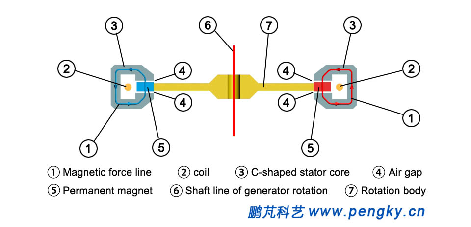
The rotor is installed in the middle of the stator, and the permanent magnet is located in the nick of the C-shaped stator core. The gap between the permanent magnet and the C-shaped stator core is a gas gap. FIG. 5 shows the axial profile of the rotor and the stator. The air gap and magnetic field line between the stator and the rotor can be clearly seen. |
|
 |
|
|
|
| Figure 5 Air gap and magnetic field line between stator and rotor | |
Figure 6 is a diagram showing the overall arrangement of the stator and the rotor. At this time, all the red magnetic poles are aligned with the C-shaped stator core. If the rotor is rotated by the angle of one magnetic pole, the blue magnetic poles are aligned with the C-shaped stator core. |
|
 |
|
|
|
|
|
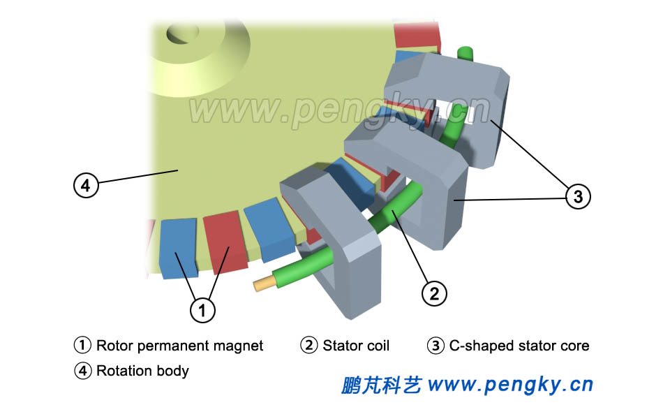
The operating principle of the transverse flux permanent magnet generator is described below. In order to clearly see the operating state, the model is simplified. Figure 7 is a partial simplified view of the model. Only three C-shaped stator cores are shown, and the stator coils are also simplified to one. |
|
 |
|
| 1- Rotor permanent magnet 2- Stator coil 3- C-shaped stator core 4- Rotor body | |
|
|
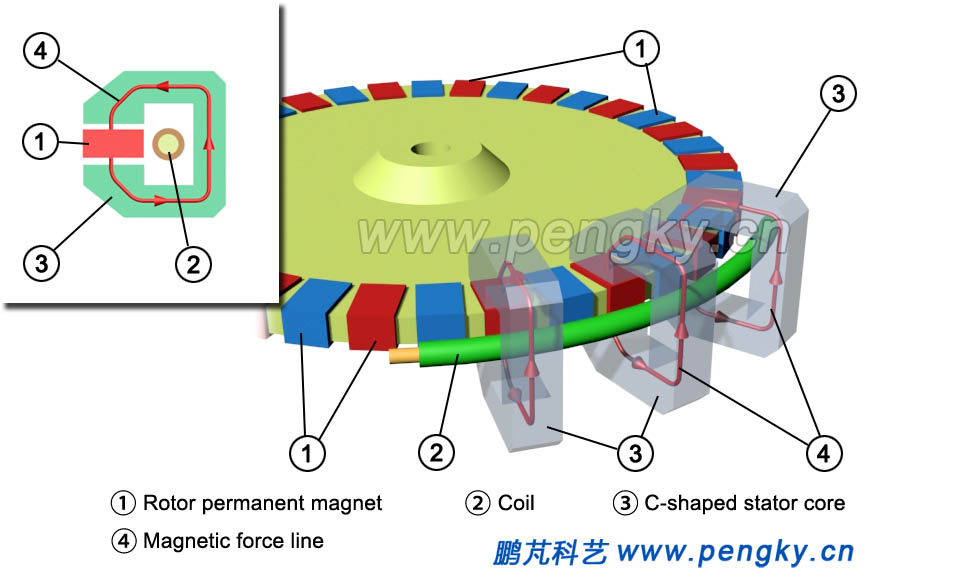
Fig. 8 is a magnetic flux state when the red magnetic pole passes through the C-shaped stator core, and the red arrow line in the figure is the direction of the magnetic flux in the C-shaped stator core, and the upper left corner thumbnail shows the state at this time more clearly. The magnetic flux states are the same in all C-shaped stator cores. |
|
 |
|
|
|
|
|
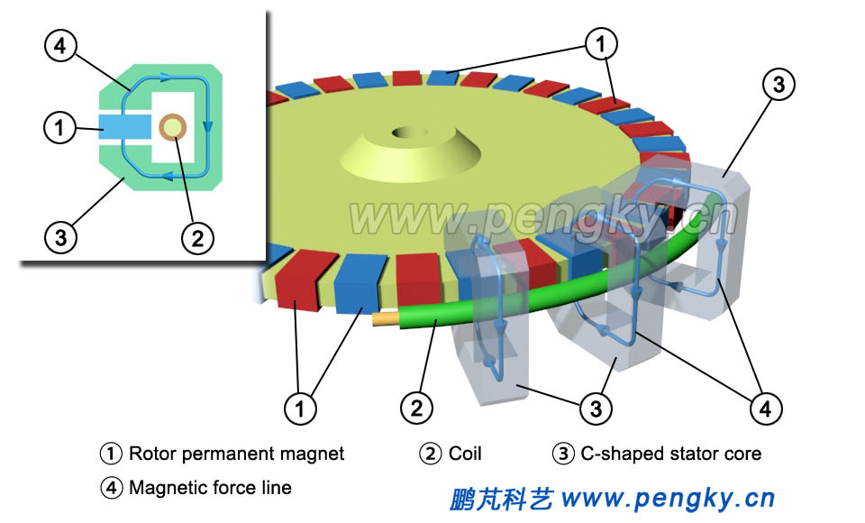
When the rotor rotates the angle of one magnetic pole, the blue magnetic pole passes through the C-shaped stator core. Figure 9 shows the magnetic flux state at this time. The blue arrow line is the direction of the magnetic flux in the C-shaped stator core, and the upper left corner thumbnail shows the state at this time more clearly. At this time, the magnetic flux direction in the C-shaped stator core is opposite to that in Fig. 8, and the magnetic flux states in all C-shaped stator cores are the same. |
|
 |
|
|
|
|
|
When the rotor rotates the angle of one magnetic pole forward again, the red magnetic pole enters the C-shaped stator core again, and returns to the state of FIG. 8, and the magnetic flux direction of the C-shaped stator core is reversed again. When the rotor rotates continuously, the direction of the magnetic flux in the C-shaped stator core will be repeatedly flipped repeatedly, and the coil wire in the surrounding magnetic field will induce an alternating current. This is the principle of power generation for transverse flux permanent magnet generators. This model is a single-phase alternator. Below is an animation that demonstrates the power generation state of this transverse flux permanent magnet generator. There are stator flux changes in the animation, as well as the direction and magnitude of the stator coil output current. |
|
| Principle animation of transverse flux permanent magnet generator | |
|
|
In the transverse flux permanent magnet generator,increasing the number of C-shaped stator cores and permanent magnet poles can achieve low-speed operation without making multiple coils. If there are 50 C-shaped stator cores and 100 permanent magnet poles, 50 laps of AC power can be sent at 1 rpm. For the structure of the ultra-low-speed generator transverse flux motor, it may be simpler to make a relatively conventional motor. |
|
| Back to Previous Page |
