
| Thin Disc Permanent Magnet Generator |
The Thin disc multi-pole permanent magnet generator is thinner than the other two types of disc generator mentioned early, in order to adapt to low windage resistance demand of the vertical axis wind turbine. This generator consists of an axial alignment of the disc stator and disc rotor. The structure of a thin disc multipole generator is described below. Figure 1 is panel stator core, there are inlaid groove evenly arranged on the side surface. |
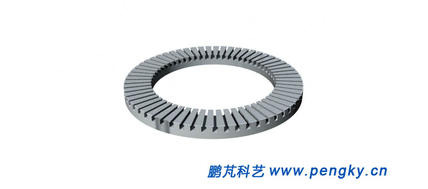 |
| Fig1 stator core |
There are stator coils arranged in a regular pattern in the iron core groove, as shown in figure 2. |
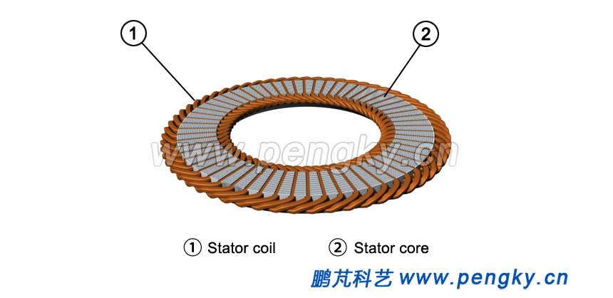 |
| Fig2 Stator core with wire coil |
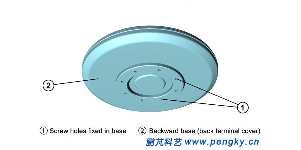
Install the stator core embedded with coil on the inner surface of the stator base (backward terminal cover), there is the main shaft of the generator installed in the center of the backward terminal cover to install the generator rotor, as shown in figure 3. |
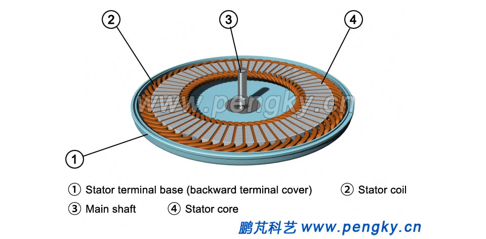 |
| Fig3 Stator with coils of disk generator |
The rotor of the disk generator is composed of multiple permanent magnetic poles, these poles are arranged in a circle and both north and south magnetic poles are arranged alternately. The permanent magnetic poles need a magnetic yoke as a magnetic force line path to fix the magnetic poles on the disk surface of the rotor magnetic yoke, which is the upper terminal cover of the generator, as shown in figure 4. |
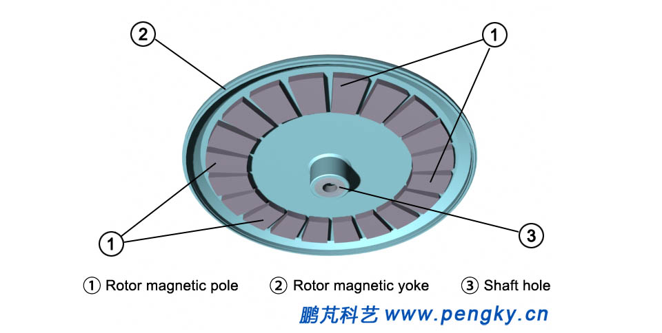 |
| Figure 4 Disk generator rotor with magnetic pole |
The upper cover center is equipped with upper and lower two bearings to ensure the rotor to rotate steadily on the main shaft, as shown in figure 5. |
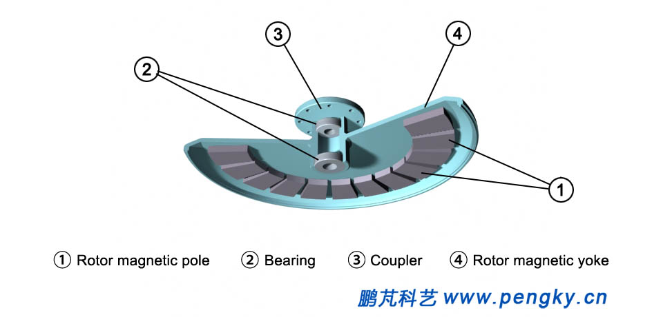 |
| FIG. 5 Sectional view of rotor of disc type generator |
When the rotor is inserted into the stator's main shaft, there is a small gap between them. The rotor can rotate freely around the main shaft, and a thin disc generator model is assembled, as shown in figure 6. |
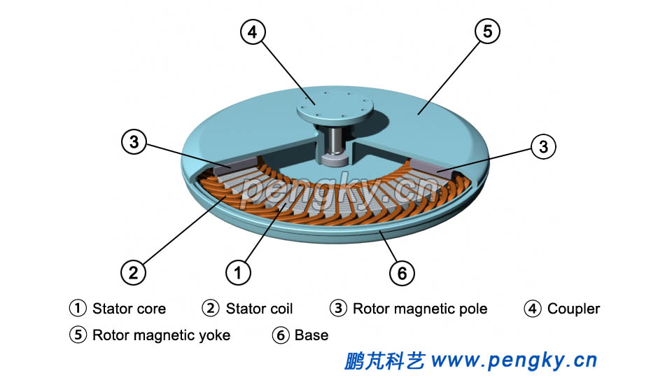 |
| FIG. 6 Sectional view of thin disc generator |
The magnetic field of the disk generator through the coil is parallel to the main shaft, naming the axial magnetic field. Only when the rotor rotates can the coil wire cut the magnetic force line to generate electromotive force, as shown in figure 7. |
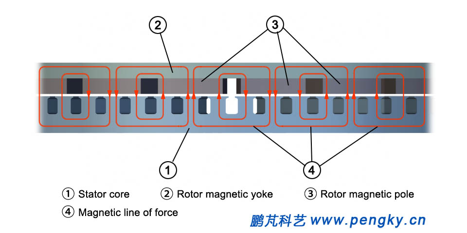 |
| FIG. 7 Sectional view of thin disc generator |
Figure 8 is Appearance diagram of thin disc generator. |
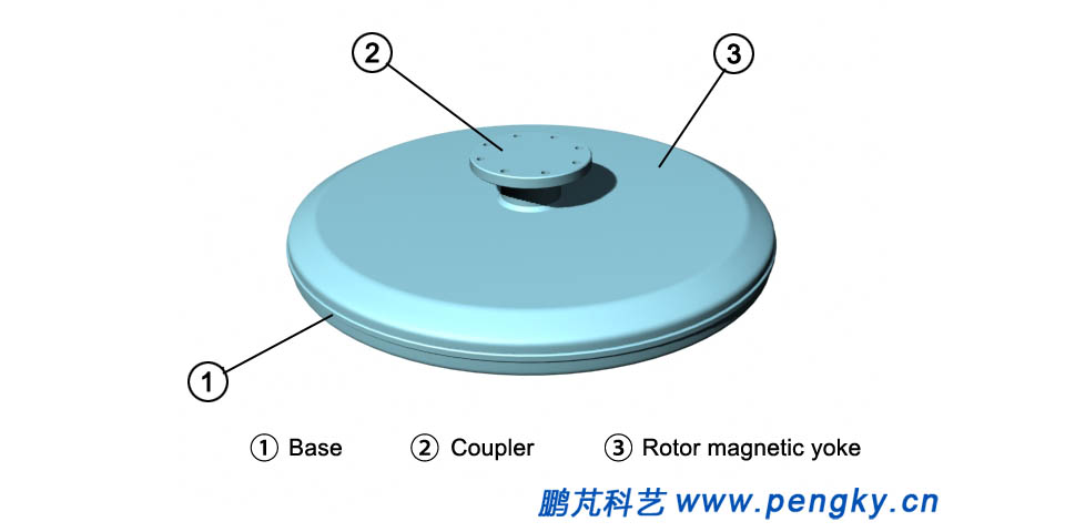 |
| Fig8 Appearance diagram of thin disc generator(1) |
FIG.9 is Appearance diagram of thin disc generator. |
 |
| FIG.9 Appearance diagram of thin disc generator(2) |
| Back to Previous Page |
