
| Magnetic Field and Flux Direction of the Generator |
Direct-drive Wind Turbine have special requirements for generator. Because of low generator speed, direct-drive Wind Turbine must be able to generate electricity at low generator speed,however, low-speed generator is usually large in bulk, and shrinking volume is the main technical requirement. It is important to reduce the diameter or shorten the thickness (disc generator). In order to achieve these goals, direct-drive Wind Turbine always use a different structure rather than conventional generator. The structure is mainly represented by the relative position of the stator and the rotor, which is the magnetic field or the magnetic circuit. The following is a brief introduction to several types of generator structures. |
| Classified by air Gap Flux Direction |
Radial air Gap Flux |
The generator relies on the relative motion of the rotor to the stator to generate electricity energy, and the gap is called an air gap between the stator and the rotor. In the conventional generator structure, the stator is on the periphery and the rotor is rotated in the middle, as shown in the right side of figure 1 below. The gap between the stator and the rotor is a cylinder, as shown in the left side figure 1 below. In the figure, the semitransparent cylinder is the air gap surface in the figure 1, and the magnetic line is perpendicular to the air gap surface, parallel to the diameter direction of the point, and is called radial air gap flux. |
| Figure 1 Radial air gap flux |
Radial air gap flux is widely used in conventional generators and generators. |
Axial air Gap Flux |
In most disc-type generators, both the stator and the rotor have a disc-type structure, and the air gap between them is a plane vertical to the generator shaft. Seeing figure 2 in right side(For clarity, the distance between the stator and the rotor is exaggerated) The left side of figure 2 is the air gap plane, it is represented by translucency. The magnetic field lines are vertical to the air gap and parallel to the direction of the rotating shaft, and are called axial air gap magnetic fluxes. |
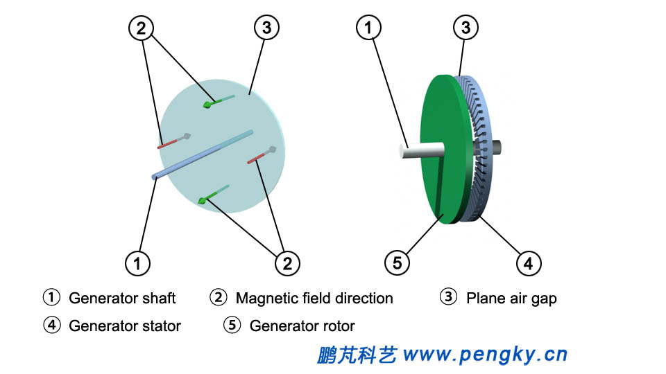 |
| Figure 2 Axial air gap flux |
Axial air gap flux is mainly used in disc generator to meet the requirements of vertical axis Wind Turbine or other special applications. |
Classified by Stator Flux Direction |
Longitudinal Stator Flux |
The magnetic field lines form a closed loop through the stator and rotor of the generator and are a surrounding magnetic flux. The plane of the circular magnetic flux of the traditional generator is parallel to the motion direction of the rotor. It is called longitudinal stator flux, briefly called longitudinal flux. Figure 3 is a schematic diagram of a longitudinal stator flux showing a magnetic flux loop in a straightened stator and rotor. |
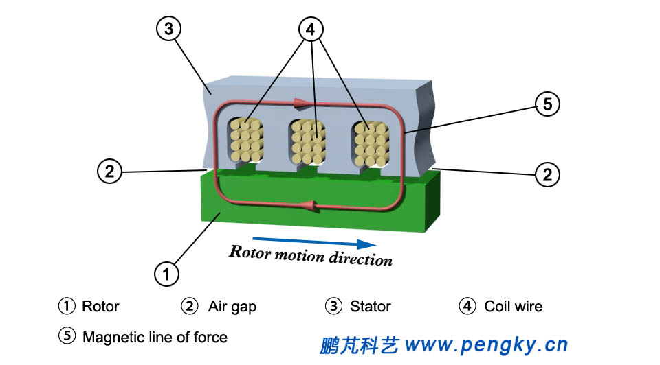 |
| Figure 3 Longitudinal stator flux |
Longitudinal stator flux is widely used in both conventional generator and conventional electromotor. |
| Lateral Stator Flux |
Transverse flux is a new type of generator structure. The left side of figure 4 is a schematic diagram of straight stator and rotor arrangement. The stator core adopts a U-shaped structure. There are two U-shaped stator cores (the whole generator has several U-shaped stator cores), and the middle of the core is the stator coil wire. There is an air gap between the rotor and the U-shaped stator core. The right side of figure 4 changes the U-shaped stator core into a translucent state, showing the magnetic lines of force in the U-shaped stator core, that is, the flux loop, the plane and rotor of the loop. The direction of motion is vertical, and this structure is called a transverse stator flux, which is simply referred to as a transverse flux. |
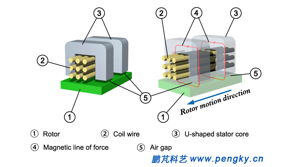 |
| Figure 4 Transverse stator flux |
The transverse stator magnetic flux has many forms and complicated structure, and is mostly used for low-speed generator. |
| Classified by the Way the Permanent Magnets are Installed |
Surface Install |
The installation of permanent magnets is divided into surface mounting and magnetism mounting. |
 |
| Figure 5 Surface mounted permanent magnets |
Polymagnetic Installation |
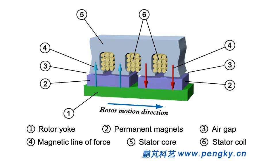
The permanent magnet in figure 6 is embedded in the rotor yoke, and its magnetic flux passes through the yoke through the air gap into the stator. The magnetic flux direction of the permanent magnet is parallel to the air gap plane and is called a magnetism mounting. |
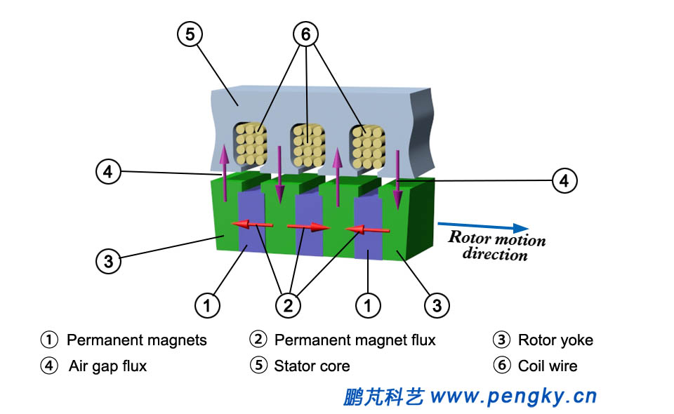 |
| Figure 6 Polymagnetic mounting permanent magnet |
The surface mounting is simpler than the magneto mounting. The permanent magnet with large magnetic flux area can be used to install the polymagnet, which is helpful to improve the air gap flux density. The magnetism-mounted permanent magnets can also be at an angle to the air gap plane or can be used in combination with surface mounting. |
| Back to Previous Page |
