
|
|
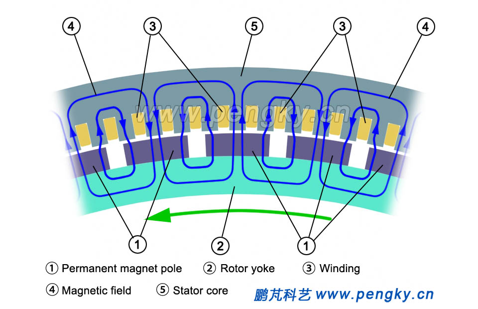
The basic structure of the inner rotor permanent magnet direct-drive wind turbine generator is the same as that of the ordinary multi-pole generator. The multi-salient pole structure is adopted, and the magnetic flux direction in the air gap is perpendicular to the motor shaft (radial magnetic flux). Compared with ordinary generator, it is only required to be lighter in structure. Figure 1 is a partial view of the stator and rotor of a multi-pole inner rotor structure with showing the direction of the magnetic flux. |
|
 |
|
| Figure 1 Magnetic circuit of the inner rotor generator | |
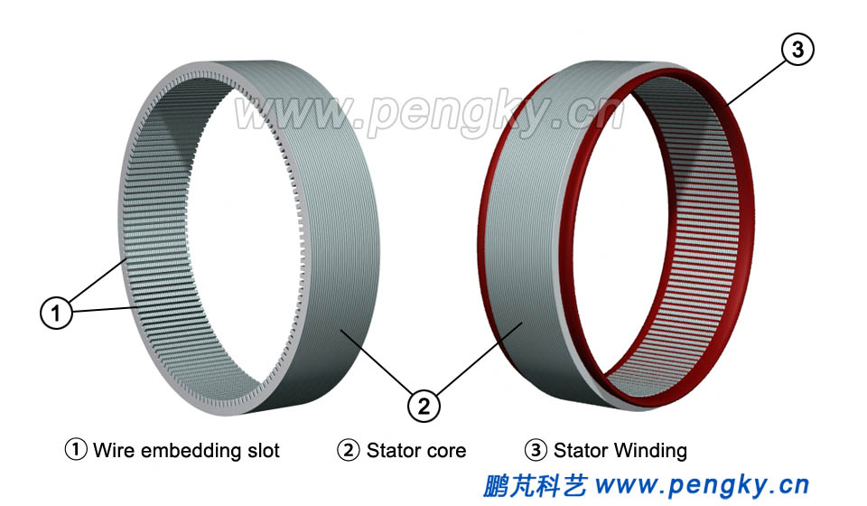
The structure and composition of the inner rotor permanent magnet direct-drive wind turbine generator model are introduced below. The generator part is introduced first. Due to the low generator speed of large wind turbines, the generator poles are about 40 pairs or more. In order to show the structure of the generator clearly, the number of poles and coil slots of the motor model is less than that of the actual direct drive generator. The stator core of the generator is made up of silicon steel sheets with good magnetic permeability, and a plurality of slots are evenly distributed on the inner circumference of the iron core (Fig. 2 left). The stator windings are embedded in the stator slots to form a three-phase winding, and each phase winding is composed of a plurality of coils, arranged according to a certain rule, as shown in Fig.2 right |
|
 |
|
| Figure 2 Stator core and winding | |
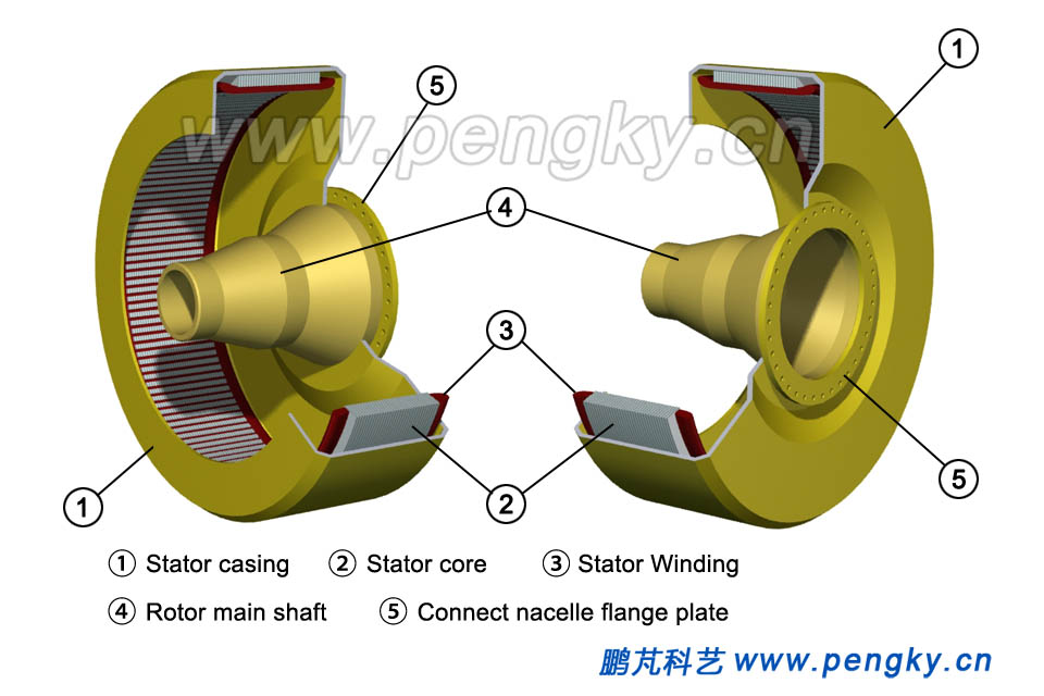
The stator (including the winding) is assembled in the stator casing. Casing has the main shaft, rotor, and the flange of the fixed generator. Figure 3 is a view from two directions. |
|
 |
|
| Figure 3 Stator mounted in the casing | |
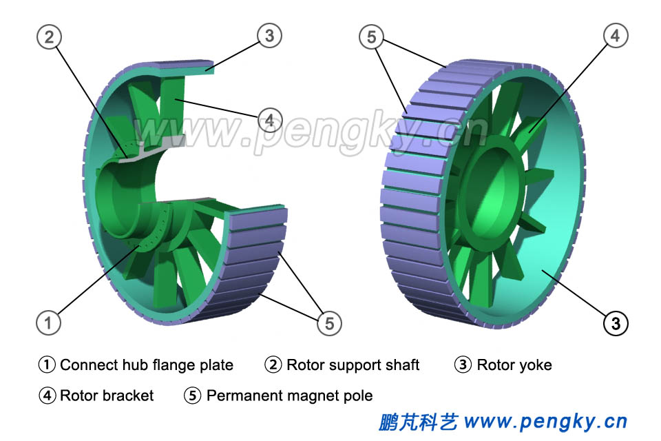
The rotor is a multi-pole structure, and a plurality of permanent magnet poles are assembled on the outer circumference of the rotor yoke to form a multi-salient rotor. The outer surfaces of the adjacent permanent magnets have opposite polarities, and the magnetic flux direction is as shown in Fig.1. The rotor yoke is fixed to the rotor support shaft by a rotor bracket, and Fig.4 is a rotor view seen from two directions. |
|
 |
|
| Fig.4 Permanent magnet salient rotor | |
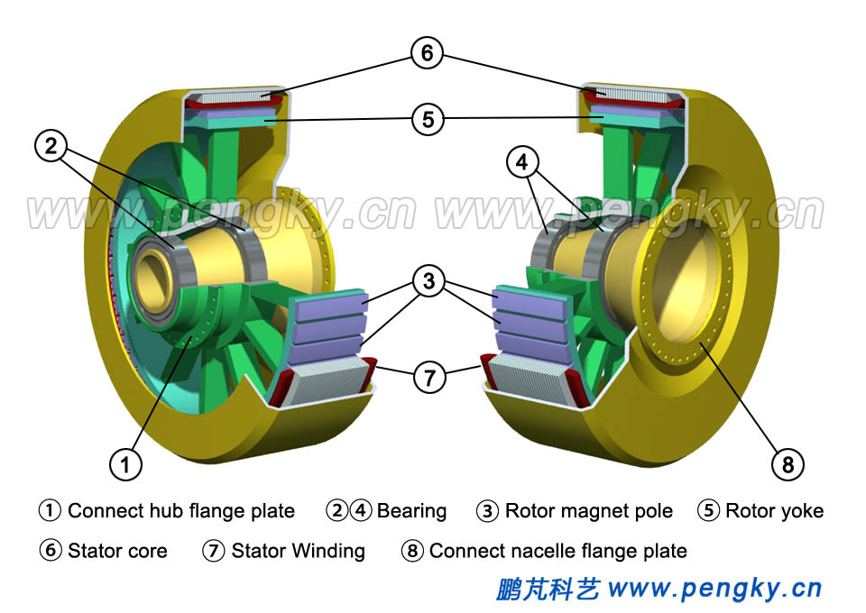
Bearing is assembled on the main shaft of the stator casing, and the rotor is assembled on the bearing. The air gap between rotor and the stator is small as less as possible but free to rotate, as shown in the cutaway view of Fig.5. When the rotor rotates, the stator winding cuts the magnetic field to induce potential. |
|
 |
|
| Fig.5 Cutaway view of a direct drive generator | |
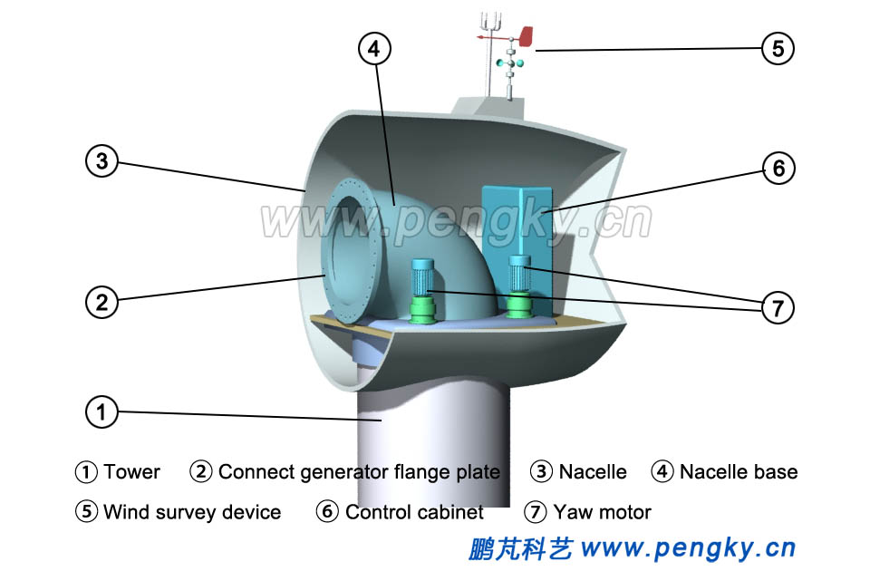
The basic components of the inner rotor direct-drive wind turbine are described below. The main process of direct-drive wind turbine erection is installing tower, nacelle, generator and hub, hoisting, hoisting, and hoisting rotor. The nacelle is installed at the top of the tower, and there is a base supporting the whole unit in the nacelle. The lower chassis of the base in nacelle is equipped with yaw motors, and the upper part of the base has a flange plate for fixing the generator stator, as shown in figure 6. There are main control cabinet, cooling system and other equipment in the nacelle, and wind survey device is on the top of the nacelle. |
|
 |
|
| Fig.6 Base and equipment in the nacelle | |
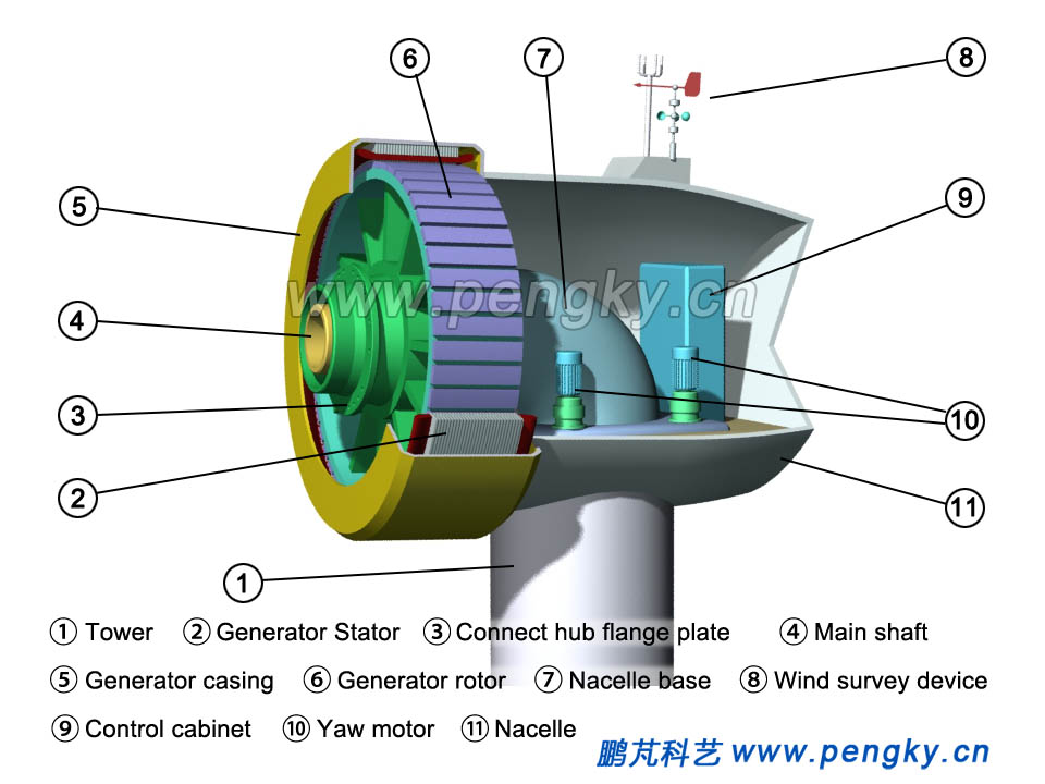
Hang the inner rotor permanent magnet generator next to the nacelle and fasten the generator flange plate to the nacelle flange plate with high-strength bolts. The generator is installed, as shown in Fig.7. |
|
 |
|
| Fig.7 Direct-drive wind turbine and nacelle | |
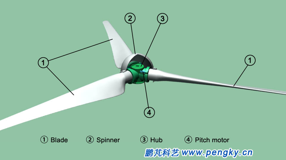
Install spinner outside the hub, install the three blades in turn on the hub, and assemble the rotor, see Fig.8. |
|
 |
|
| Fig.8 Direct-Rotor of drive wind turbine | |
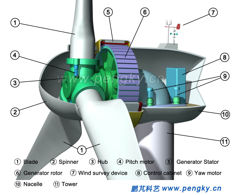
Hang the rotor next to the direct-drive generator, fasten the generator flange plate which connects to the hub and the flange plate on the rotor hub with high-strength bolts, and the lifting is completed, as shown in Fig.9. Connect all signal cables, control cables and pipes in the nacelle, connect the power cables to the generators, and the wind turbine installation is over. It can be run after commissioning. |
|
 |
|
| Fig.9 Cutaway view of the inner rotor direct-drive wind turbine | |
The following is an animation to run this inner rotor direct-drive permanent magnet wind turbine. |
|
| Inner rotor direct-drive permanent magnet wind turbine animation | |
|
| Back to Previous Page |
