
Intermediate Stator Disc Generator |
Due to the short axial dimension and large diameter of disc generator, it is easy to make a multi-pole structure with high power and mass ratio, besides disc generator can be made thinner. So wind resistance can be low mounted on the runner of the vertical axis wind turbine and it is the preferred model for direct drive vertical axis wind turbine. The stator and rotor of the disc generator have a flat disc structure with axial air gap flux, and they are arranged alternately in the axial direction. The following describes a direct drive intermediate stator disc wind turbine through a model. Figure 1 is a disc stator core. Since the magnetic field lines of the disc generator are axially oriented through the stator windings and run around the shaft, as the motor rotates, the silicon steel sheets of the stator are wound, and there are winding grooves on both sides. |
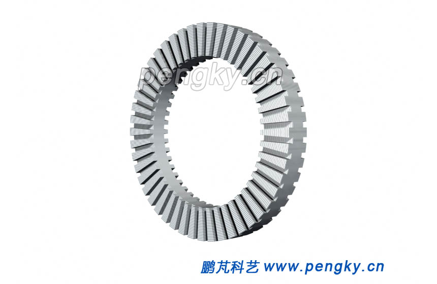 |
| Figure 1 Disc Stator Core |
The stator windings are distributed in the stator slots and connected in a three phase arrangement, seeing Figure 2 below. |
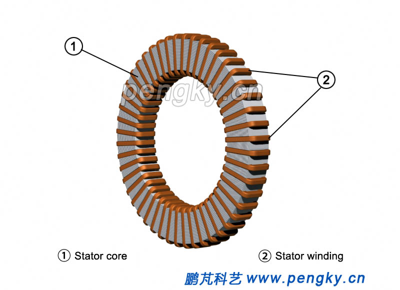 |
| Figure 2 Disc stator core and winding |
The disc stator core is fixed on the bracket of the base, as shown in Figure 3. |
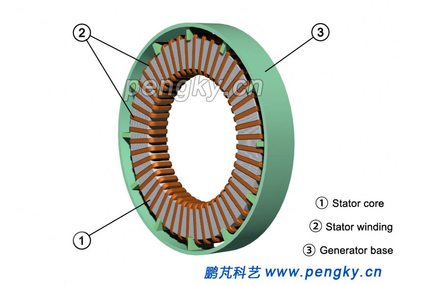 |
| Figure 3 Disc stator fixed to the base |
The Disc rotor is mounted on both sides of the stator, and composed of yoke and magnetic poles, which is made of permanent magnet. Figure4 is a rotor diagram on the left. |
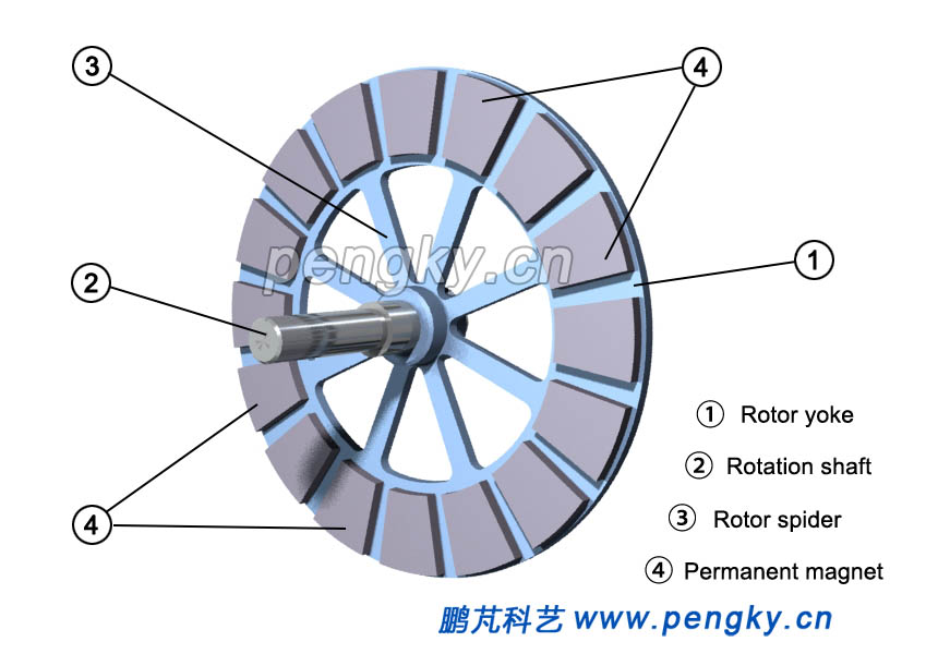 |
| Figure 4 Disc rotor |
Figure 5 below is showing the distribution of magnetic in disc rotor poles |
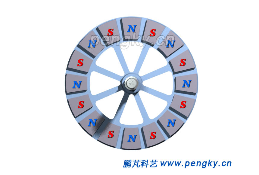 |
| Figure 5 Distribution of Magnetic poles on the disc rotor |
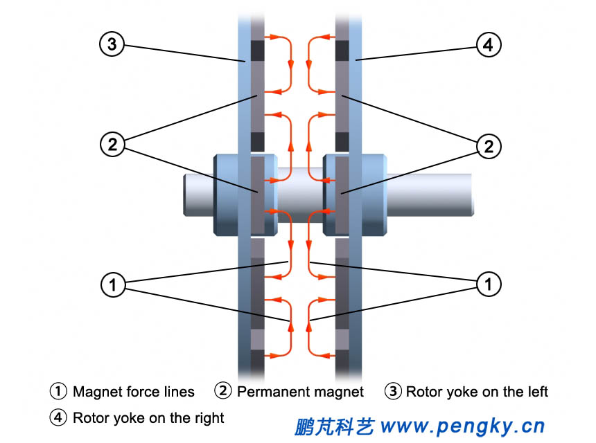
The right rotor structure is the same as that on the left, but only in different reverse side. Figure 6 is a diagram of the magnetic field lines between the left and right rotors (stator is hidden). It can be seen that the direction of the magnetic force lines is axial while passing through the plane of the stator weaving groove (or air gap) is axial, so we can say the disk generator uses an axial magnetic field. |
 |
| Figure 6 Magnetic field line of the disk rotor |
In order to see the direction of the magnetic field lines more clearly, figure 7 shows the trend of the magnetic field lines a bit on the side. |
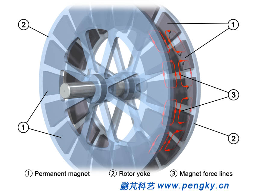 |
| Figure 7 Magnetic field line of the disk rotor |
The rotor is mounted on both sides of the stator, and there is an air gap between them, which constitutes the disc generator structure of the rotor on both sides of the intermediate stator, as shown in Figure 8. |
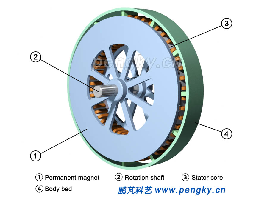 |
| Figure 8 Disc rotor and disc stator |
The left and right terminal caps are mounted, and figure 9 shows the assembled permanent magnet intermediate stator disc generator. |
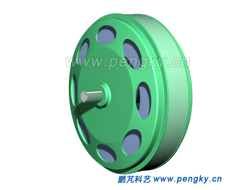 |
| Figure 9 Permanent intermediate stator disc generator model |
Figure 10 is a cross-sectional view of a permanent magnet intermediate stator disk generator. |
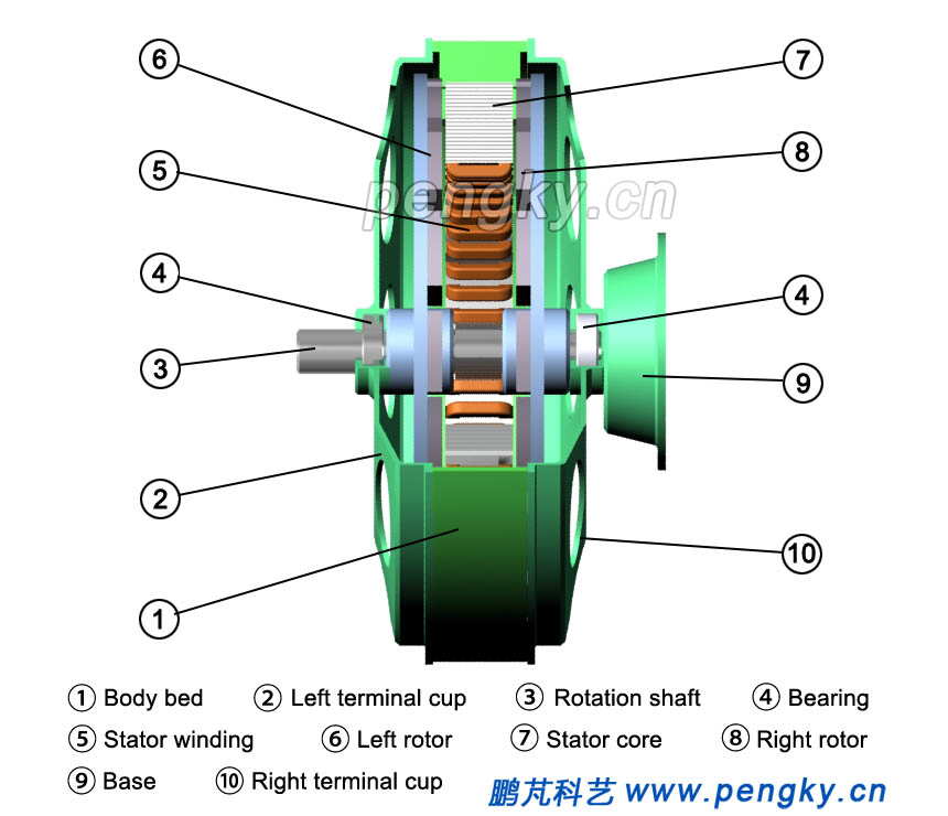 |
| Figure 10 Sectional view of permanent magnet intermediate stator disc generator |
Figure 11 is showing a side cross-sectional view of the internal structure with hidden of right rotor. |
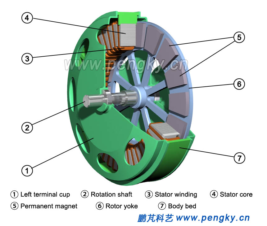 |
| Figure 11 Sectional view of permanent magnet intermediate stator disc generator |
| Back to Previous Page |
