
Intermediate Rotor Disc Generator |
|
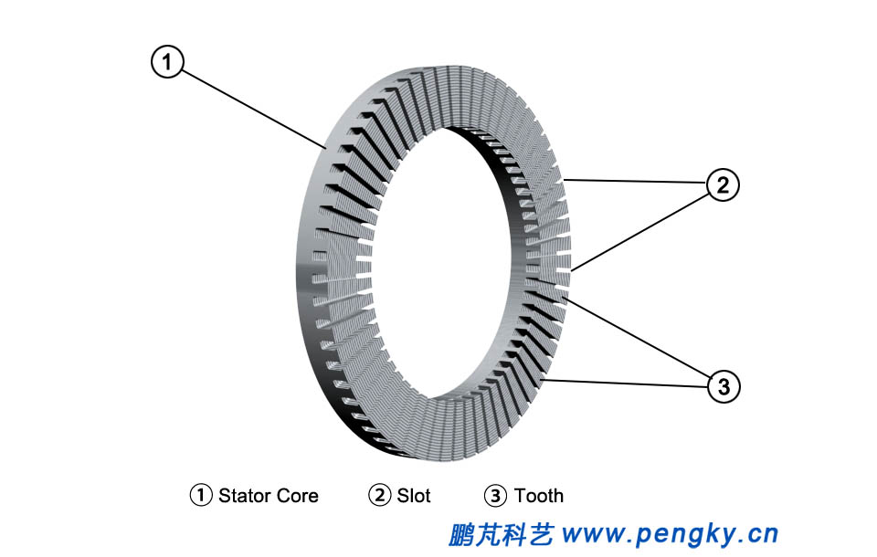
Due to the short axial dimension and large diameter of disc generator, it is easy to make a multi-pole structure with high power and mass ratio, besides disc generator can be made thinner. So wind resistance can be low mounted on the runner of the vertical axis wind turbine and it is the preferred model for direct drive vertical axis wind turbine. The stator and rotor of the disc generator have a flat disc structure, with axial air gap flux, and they are alternately arranged in the axial direction. The following describes a direct drive intermediate rotor disc wind turbine through a model. Both left and right part compose of the stator core of the intermediate rotor permanent disk generator. Figure1 is showing a disk type stator. Since the magnetic field lines passing through the stator windings are axially oriented and run around the shaft as the motor rotates. , the silicon steel sheet of the stator is wound, and there are winding grooves on one side. |
|
 |
|
| Figure 1 Disc Stator Core | |
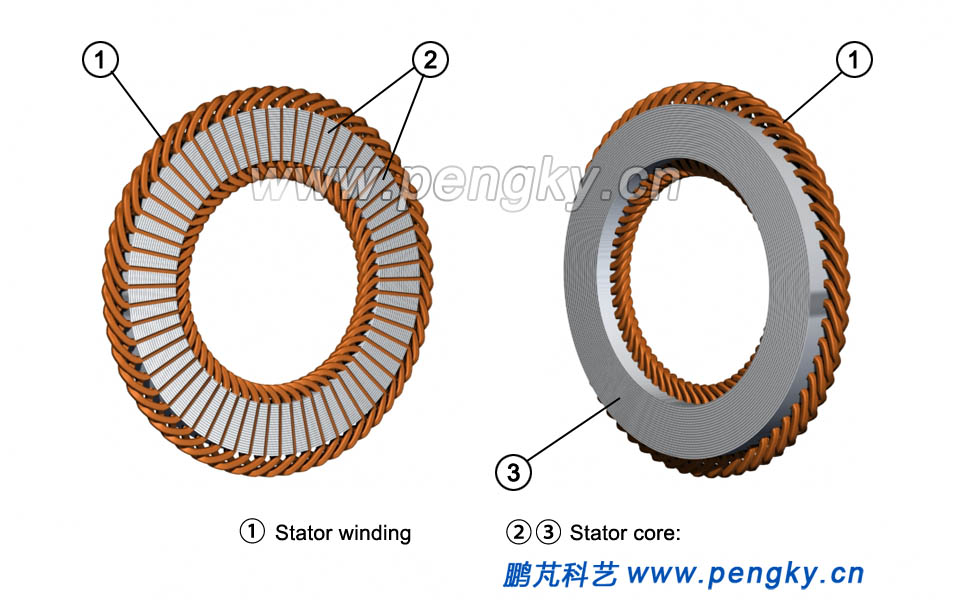
The stator windings are distributed in the stator slots, and the single windings are fan-shaped according to the three-phase arrangement, showing in figure 2 below. |
|
 |
|
| Figure 2 Disc stator core and winding | |
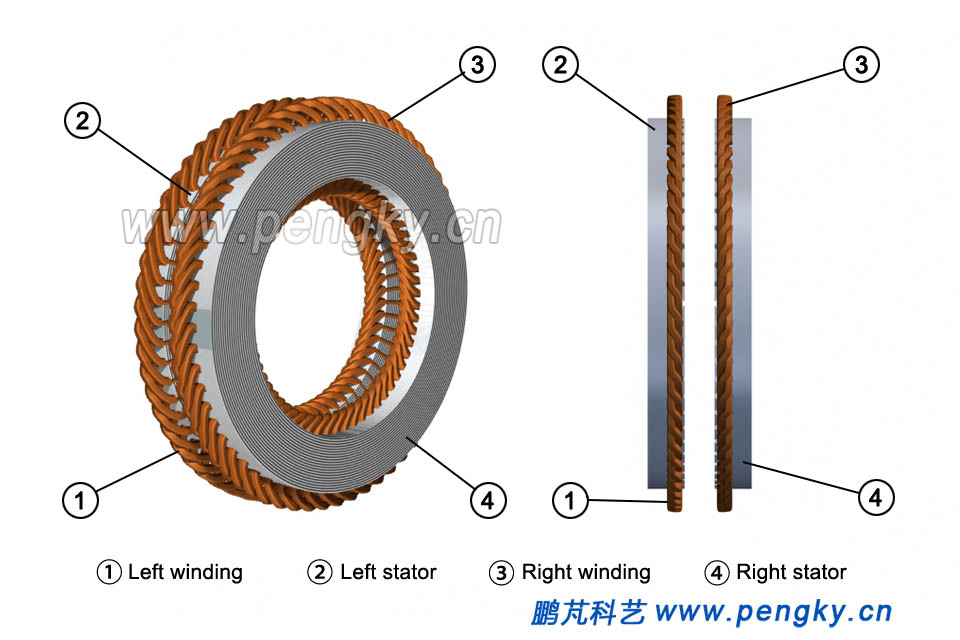
There are two stator cores, with the same structure as the left stator core, but only in different reverse side, seeing figure 3. |
|
 |
|
| Figure 3 Left and right disc stator cores | |
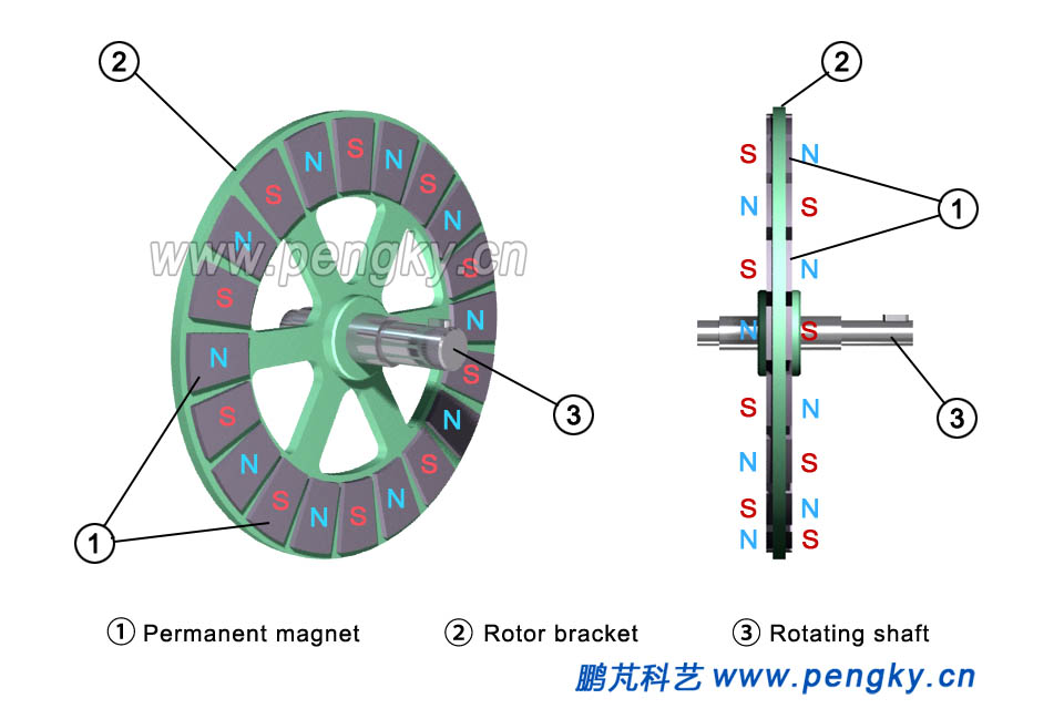
The rotor is composed of magnetic poles made in permanent magnet, and it is fixed on a rotor holder made in non-magnetic material. Figure4 is a structural view of the rotor. The magnetic poles of each magnet is on both sides of the field spider, seeing figure 4. |
|
 |
|
| Figure 4 Disc intermediate rotor | |
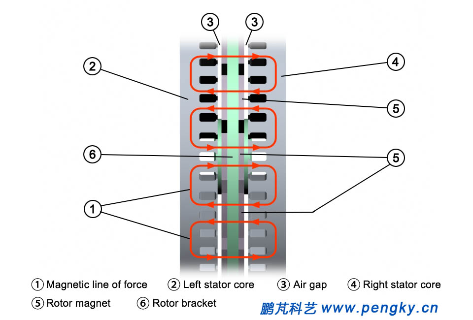
Figure 5 shows the direction of the magnetic force line between the rotor and the stator, and it can be seen that axial is the direction of the magnetic force line in the plane (or air gap plane) through the stator inlay slot. |
|
 |
|
| Figure 5 direction of magnetic force line of the middle rotor | |
Figure 6 is a layout view of the rotor and the stator in the axial direction. |
|
 |
|
| Figure 6 Layout of the middle rotor and stator | |
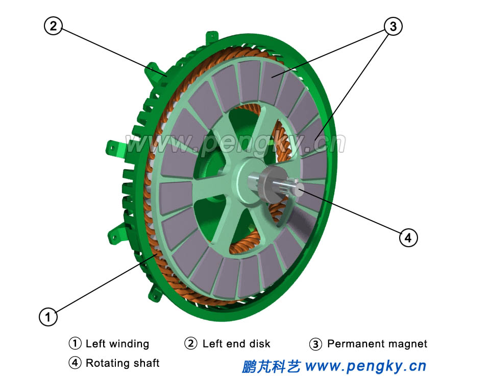
First fix the left stator in the left terminal cover and then install the rotor, seeing figure 7. |
|
 |
|
| Figure 7 Left stator and rotor | |
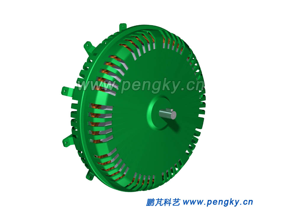
Then fix the right stator in the right terminal cover, and fasten and fix the left and right bearing terminal-shield as a result the generator is assembled completely. Figure 8 is an external view of the generator. |
|
 |
|
| Figure 8 Intermediate rotor disc generator | |
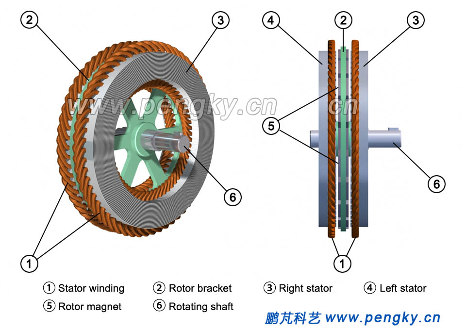
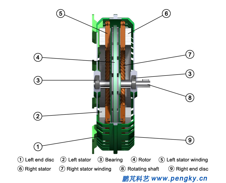
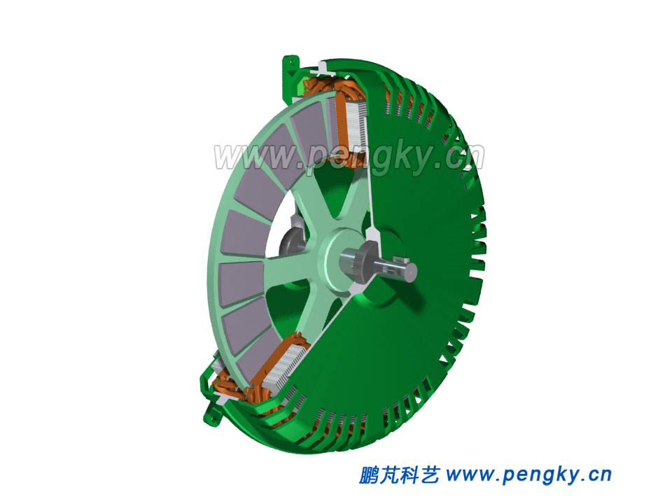
Figure 9 is a cross-sectional view of the intermediate rotor disc permanent magnet generator. |
|
 |
|
| Figure 9 Intermediate rotor disc generator profile-1 | |
Figure 10 shows the cross-section drawn. |
|
 |
|
| Figure 10 Intermediate rotor disc generator profile-2 | |
Please watch the 3D animation of the direct drive intermediate rotor disc permanent magnet generator |
|
| Direct drive intermediate rotor disc permanent magnet generator 3D animation | |
|
|
| Back to Previous Page |
