
|
|
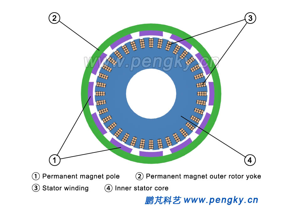
The outer rotor motor is characterized in that the stator is fixed in the middle position of the shaft, and the rotor rotates on the periphery of the stator, which is also a radial air gap flux structure. Compared with the inner rotor structure, the rotor and the stator replace their position for each other. Figure. 1 is a plane view of an outer rotor generator. The stator is referred to as an inner stator inside the motor, and the rotor is outside the motor, which is referred to as an outer rotor. |
|
 |
|
| Figure 1 Plane view of the outer rotor generator | |
The following is the outer rotor generator plane animation. |
|
The outer rotor generator plane animation |
|
|
|
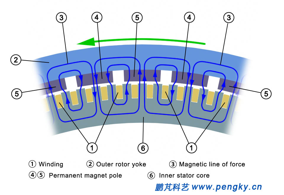
Figure 2 is a partial view of the stator and the rotor. The outer circumference of the inner stator core is evenly distributed with a lot of slots for inserting the windings. The inner circumference of the outer rotor is provided with permanent magnet poles. And the magnetic flux direction is as shown. When the rotor rotates, the winding cuts the magnetic field to induce potential. |
|
 |
|
| Figure 2 Magnetic circuit of the external rotor electric machine | |
Direct-Drive Outer Rotor Permanent Magnet Wind Turbine |
|
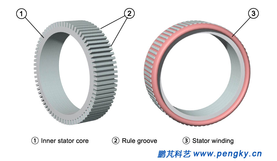
The composition and structure of the direct-drive outer rotor permanent magnet wind turbine are described below. The structure is introduced by a permanent magnet external rotor generator model. The left figure of Figure 3 is the inner stator core diagram. The stator core is laminated with silicon steel plate with good magnetic permeability. There are many slots on the outer circumference of the stator core, the windings of the generator are embedded in the slots. And the windings are distributed according to the three-phase distribution law (Chart. 3 right). Generally, the outer rotor of a large direct-drive wind turbine generator has 30 to 40 pairs of magnetic poles, and the number of stator slots is about 180 to 240. In order to clearly show the construction of the inner stator core, the number of coil slots in this model is much less than that of an actual direct drive generator. |
|
 |
|
| Figure 3 Stator core and winding in a direct drive generator | |
The stator core is installed on the stator bracket. The stator frame has a flange mounted to the nacelle frame at one end, and the outer rotor shaft is also the main shaft of the wind turbine at the other end of the stator shaft The main shaft bears the weight and wind force of the entire wind rotor and the outer rotor, and the main shaft and the flange have high strength (Fig. 4). |
|
 |
|
| Fig.4 Inner stator structure of a direct drive generator | |
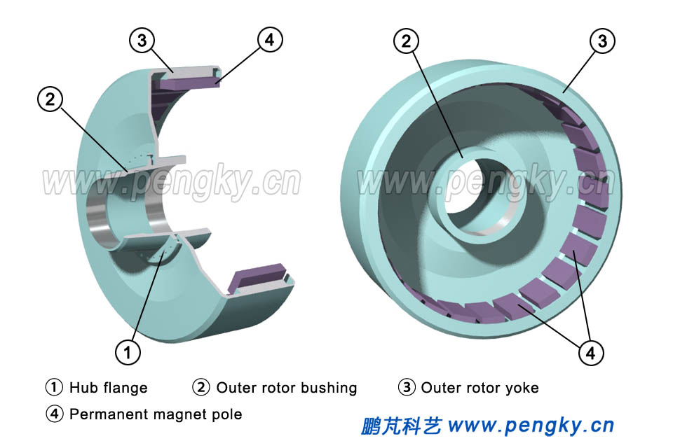
Figure 5 is a cross-sectional view of the outer rotor structure, with showing its structure in two directions. The outer rotor is like a barrel sleeve on the offside of the stator, made of a ferromagnetic material. The inner circumference of the "barrel" is fixed with a magnetic pole made of a permanent magnet. The "barrel" is the magnet yoke of the rotor. One of the advantages is that the magnetic pole is relatively easy to fix, does not fall off due to centrifugal force, and the outer rotor yoke is fixed on the rotor sleeve. |
|
 |
|
| Fig.5 Outer rotor structure of a direct drive generator | |
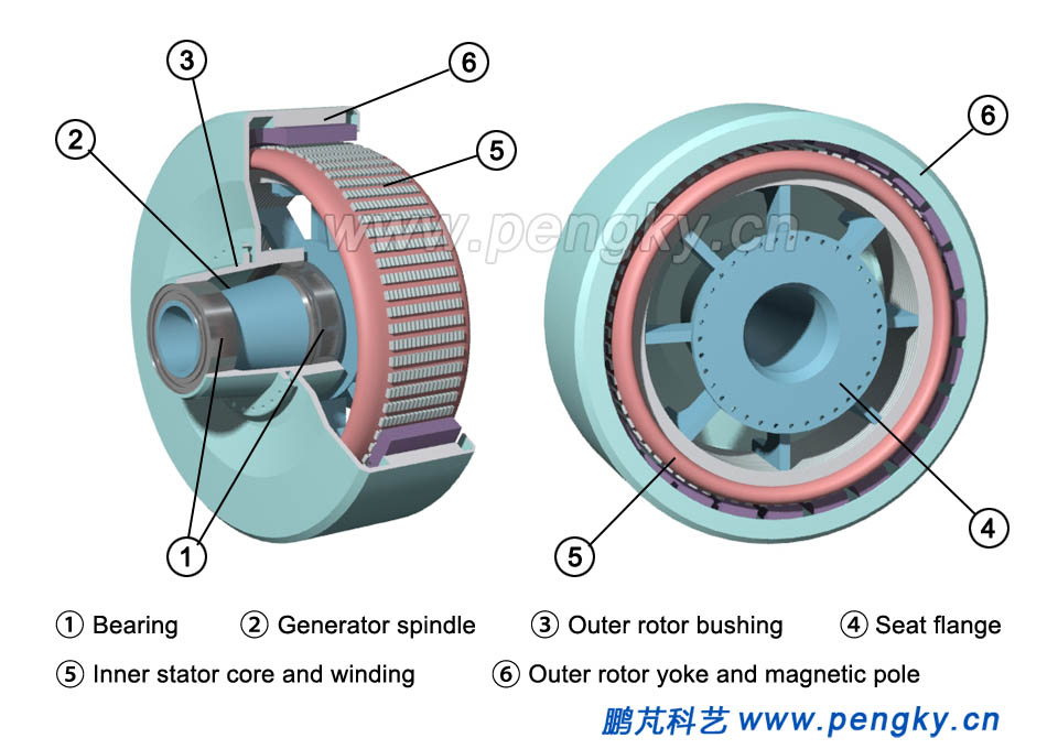
The outer rotor is installed on the generator main shaft to form an outer rotor generator. Figure 6 shows the structure from two directions. The outer rotor sleeve not only fixes the outer rotor, but also installs the entire wind rotor and is subjected to a large load. So it is mounted on the generator main shaft through two large bearings. |
|
 |
|
| Fig.6 Direct drive external rotor generator structure | |
Direct-Drive Outer Rotor Permanent Magnet Wind Turbine |
|
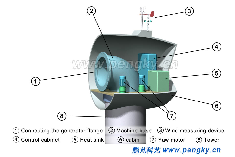
When the wind turbine is installed, the nacelle is first hoisted at the top of the tower. The carcass is fixed in the nacelle. The flange of the direct-drive generator is installed on the carcass (Figure. 7). |
|
 |
|
| Fig.7 Nacelle carcass frame | |
The generator is hoisted to the nacelle. The generator nacelle end flange is fastened to the frame flange (Figure 8). |
|
 |
|
| Fig.8 Installing a direct drive generator | |
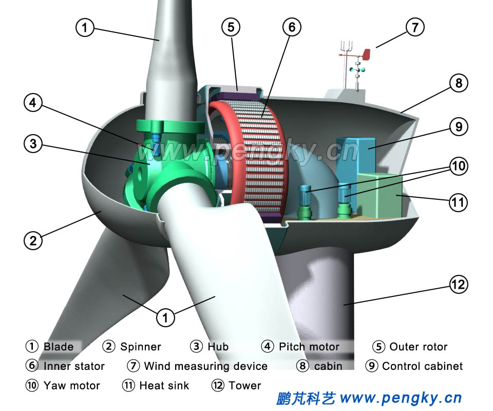
The blade is installed on the hub to form a wind rotor. The wind rotor is hoisted to the side of the generator. The high-strength bolt is used to fix the rotor hub flange and the outer rotor connecting hub flange. And the wind rotor and the outer rotor can rotate synchronously. There is a spinner on the outside of the hub, and the nacelle also has electrical cabinet, control system, motor cooling system, wind measuring system and so on. Figure 9 is a structural diagram of a model of an outer rotor direct drive permanent magnet wind turbine. |
|
 |
|
| Fig.9 External rotor permanent magnet direct drive wind turbine | |
Let's look at the animation of an external rotor permanent magnet direct-drive wind turbine. It is clear how the outer rotor runs synchronously with the rotor. |
|
External rotor permanent magnet direct drive wind turbine animation |
|
|
|
| Back to Previous Page |
